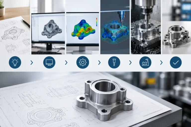


In the early 1990s, I was standing in front of a room of experienced drafters, each with fifteen or twenty years of experience, to introduce our first 3D solid modeling system. I will never forget the look on one man’s face. He was the best draftsman in the building. He could draw a perfect section view with his eyes half closed, and he leaned over to the colleague next to him and whispered, loud enough for me to hear: “So we are going to build the part first, and then draw it?”
Yes. Exactly that. And it changed everything.
That whispered question captures the whole difference between 2D and 3D CAD better than any technical comparison. In 2D, the drawing is the product of the design. In 3D, the model is the product, and the drawing is a report on it. In this guide I will walk you through what each approach really is, where each one wins, where each one fails, and how to decide, as a student, a designer or a manager, how much of each you need in today’s mechanical engineering world.
If you are new to the field, you may want to start with What Is Mechanical CAD (MCAD)? A Complete Beginner’s Guide for the basic vocabulary.
The Short Answer
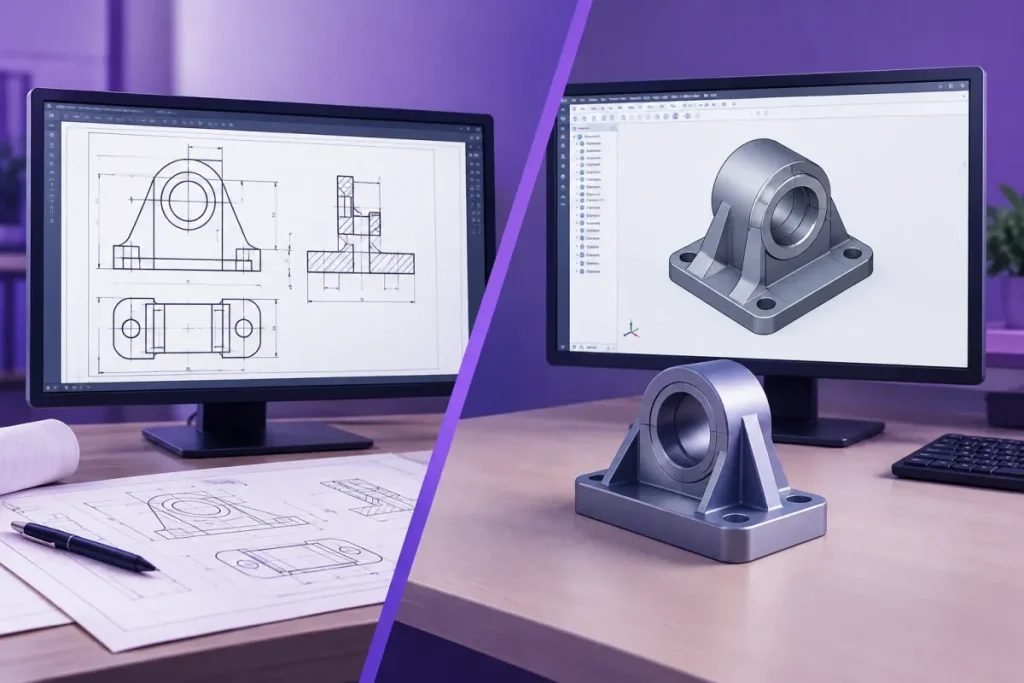
- 2D CAD represents a product as a set of flat views (top, front, side, sections) drawn with lines, arcs and text. Each view is a separate piece of geometry. The relationship between the views exists only in the designer’s mind.
- 3D CAD represents a product as a single three-dimensional model. Views, sections and measurements are derived from that model. The relationship between the views exists inside the software.
Modern mechanical engineering is built on 3D models, but 2D has not disappeared. It survives as the dominant format for manufacturing documentation, for quick layouts, for schematics and for a huge archive of legacy data. The most useful skill today is to understand both and to know which one to use when.
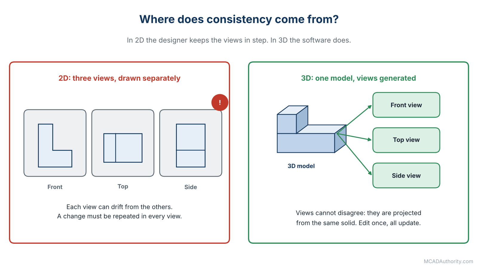
Figure 1. In 2D the designer keeps views consistent; in 3D the software does.
What 2D CAD Really Is
2D CAD is the digital descendant of the drafting board. You draw lines, arcs and circles on a flat plane. You group views according to the conventions of orthographic projection: the front view, a top view placed above it, a side view placed beside it, plus sections and details when you need them.
Two projection conventions exist, and you will meet both in your career:
- First-angle projection, common in Europe and much of the world, places the top view below the front view.
- Third-angle projection, common in the United States and Canada, places the top view above the front view.
Every professional drawing carries a small symbol indicating which one applies. I have seen expensive parts scrapped because someone misread it. The principles of reading and creating these views are covered in Mechanical Engineering Drawings: A Complete Guide.
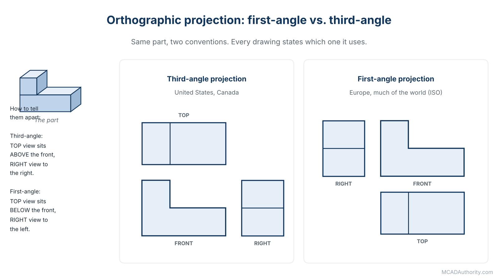
Figure 2. First-angle versus third-angle projection: same part, two conventions.
What 2D does well
Credit where it is due. 2D CAD has strengths that no one should dismiss:
- Speed for simple work. A flat plate with a few holes can be drawn in minutes.
- Low barrier to entry. The concepts are intuitive, the software is lighter and the learning curve is gentler.
- Light hardware requirements. Almost any computer runs it.
- Universal communication. A 2D drawing can be read, printed and shared by anyone, anywhere, without special software.
- Flexibility. You can sketch an idea or change a layout without worrying about a feature tree.
- Mature tooling. Standards, symbol libraries and workflows have been refined over decades.
Where 2D struggles
The weaknesses appear as soon as products become complex:
- No single source of truth. Every view is independent, so inconsistencies creep in.
- Changes multiply. A modification may need to be repeated in each view and in each related drawing.
- No fit checking. You can’t test whether parts collide or whether a mechanism can move.
- Manual calculations. Mass, center of gravity and volume must be computed by hand.
- Manual lists. The bill of materials, hole tables and cut lists are assembled by people, with all the errors that implies.
- Visualization depends on skill. Understanding a complex assembly from flat views demands a trained spatial imagination.
What 3D CAD Really Is
When people say “3D CAD”, they may mean one of three quite different things, and it is worth knowing the difference.
- Wireframe models. Only edges, no surfaces and no volume. They were an early step and are rarely used today for mechanical design.
- Surface models. Mathematical skins that describe the outside of an object, ideal for complex curved shapes such as car bodies, bottles or aerodynamic covers. They are explored in Surface Modeling in Mechanical CAD: A Complete Guide.
- Solid models. Closed volumes that know what is inside and what is outside. This is the foundation of modern mechanical design, because a solid has volume, mass and can be cut, assembled and analyzed.
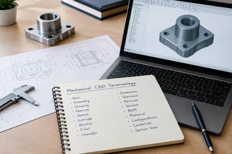
When we talk about 3D CAD in mechanical engineering, we nearly always mean solid modeling, often combined with surfaces where needed. Inside the software, the model is typically stored as a boundary representation (B-rep) with faces, edges and vertices, together with a history of features in parametric systems. These terms are defined in Essential Mechanical CAD Terminology Every Designer Should Know.
What 3D does well
- One model, many outputs. Drawings, bills of materials, renderings, simulation, machining and printing all derive from the same source.
- Automatic consistency. Views cannot disagree because they all come from one body.
- Cheap change. Modify a dimension once and everything linked updates.
- Early problem detection. Interference, clearance and motion can be checked before anything is made.
- Instant physical data. Volume, mass, center of gravity and moments of inertia come directly from the model.
- Better communication. A customer, a buyer or a technician understands a 3D model immediately, without needing years of drawing training.
- Direct manufacturing links. CNC machines, 3D printers, laser cutters and inspection systems can consume the model data.
- Reuse. Parts, features and entire sub-assemblies can be copied, configured and adapted.
Where 3D struggles
Honesty matters here too, because 3D is not free of problems:
- Steeper learning curve. You must learn modeling strategy, not just drawing.
- Heavier hardware. Large assemblies demand memory, a fast processor and a good graphics card.
- Setup effort. Templates, libraries and standards need to be organized before you gain the full benefit.
- Fragility. Poorly built models break when edited. How to Build a Clean and Reliable CAD Feature Tree is dedicated to avoiding that.
- Over-modeling. Designers sometimes model every thread and every tiny radius when a simplified representation would do.
- Data management needs. Many files, many references and many revisions require discipline and often a PDM system.
Side-by-Side Comparison
| Criterion | 2D CAD | 3D CAD |
|---|---|---|
| What you create | Flat views of a product | A complete digital solid of the product |
| Relationship between views | Maintained by the designer | Maintained automatically by the software |
| Making a change | Edit each affected view | Edit the model, drawings update |
| Checking fit and motion | By eye, or with physical prototypes | Interference and motion analysis in software |
| Mass and volume | Manual calculation | Automatic |
| BOM and lists | Usually manual or semi-automatic | Generated from the assembly |
| Learning curve | Gentle at first | Steeper at first, rewarding later |
| Hardware demand | Low | Moderate to high |
| Communication with non-specialists | Needs trained readers | Immediate and visual |
| Link to CNC, 3D printing, simulation | Indirect | Direct |
| Best use | Simple parts, layouts, schematics, legacy work | Products, machines, assemblies, anything complex |
The Real Question: What Is Being Lost When You Draw in 2D?
I want to share a mental exercise I use in training. Take a simple machine part, a bracket with four holes, two bends and a slot. Ask yourself: how many facts about this part are stored in the file?
In 2D, the answer is: only the lines you drew. Those lines imply a shape, but the file does not know it is a bracket. It does not know the holes are through-holes. It does not know the bends have a radius that depends on the material thickness.
In 3D, the file knows the thickness, the material, the bend radius, the hole diameters, the volume, the mass and the unfolded flat pattern. It knows how each feature was created and in what order. That extra information is the real asset, and it is what makes later changes, analysis and manufacturing possible.
This is why I tell managers that the question is not “which one draws faster?” but “which one stores more of what my company knows?“
Where 2D Still Matters (And Will for a Long Time)
Anyone who tells you that 2D is dead has not spent time in a real workshop. Here is where it remains essential.
1. Manufacturing drawings
Even when a part starts as a 3D model, the drawing is still the most widely accepted contractual document between designer and manufacturer. It carries dimensions, tolerances, surface finishes, notes, material specifications and inspection requirements that a bare model does not communicate on its own. Even the evolving practice of 3D annotation, covered in Model-Based Definition (MBD) and 3D Product Manufacturing Information (PMI), has not yet replaced the drawing everywhere.
In other words: in a 3D workflow, 2D has not vanished; it has been demoted from creator to output.
2. Layouts and concept work
Plant layouts, machine footprints and early concept studies are often faster in 2D. You do not need a perfect model to decide where a conveyor will sit in a hall.
3. Schematics and diagrams
Hydraulic circuits, pneumatic diagrams, flow charts and process diagrams are intrinsically 2D, and the software for them is built around symbols and connections.
4. Simple flat parts
A gasket, a plate or a simple laser-cut profile can be created as a clean 2D outline in a few minutes, and many cutting machines accept 2D files directly.
5. Legacy and maintenance
Companies hold decades of 2D drawings. Reading, revising and extracting information from them is a daily task. Anyone claiming that all of this can be converted overnight has never tried.
6. Quick checks and field work
Marking up a drawing on site, adjusting a note or correcting a dimension is often far faster in 2D.
7. Mixed supply chains
Not every supplier has 3D capability. Some small shops still work best from PDFs and printed drawings. You must meet them where they are.
Where 3D Is Now Non-Negotiable
On the other side, there are situations where staying in 2D is simply a competitive handicap.
- Complex assemblies. Once a product has dozens or hundreds of parts, only a 3D assembly lets you verify fit and clearance reliably.
- Moving mechanisms. Linkages, cams, gearboxes and actuators need motion checks.
- Plastic and cast parts. Draft angles, ribs, shrinkage and tooling demand 3D geometry.
- Sheet metal. Accurate flat patterns come from the 3D bent model.
- Simulation. Stress, thermal and flow analysis require a solid or surface model. See Finite Element Analysis (FEA): Fundamentals for CAD Designers.
- Additive manufacturing. 3D printing starts from a 3D file by definition. Design for Additive Manufacturing (DfAM): A Complete Guide covers what happens next.
- CNC machining. Modern CAM systems build toolpaths directly on the model.
- Configurable products. Families of products with variants are far easier with parametric models and design tables.
- Customer demand. Many customers now require 3D data as part of the deliverables.
The Hybrid Reality of Today’s Offices
In practice, almost no one lives in a pure 2D or pure 3D world. A typical modern workflow looks like this:
- Concept in sketches, sometimes in 2D layout drawings.
- Detailed design in 3D parts and assemblies.
- Analysis on the 3D model.
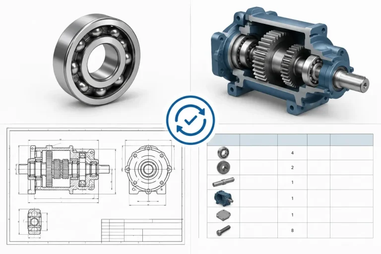
- Documentation as 2D drawings generated from the 3D model, with additional hand-placed annotations.
- Manufacturing data as 3D files, such as STEP, plus 2D drawings or flat patterns.
- Archive of both the model and the released drawing, under revision control.
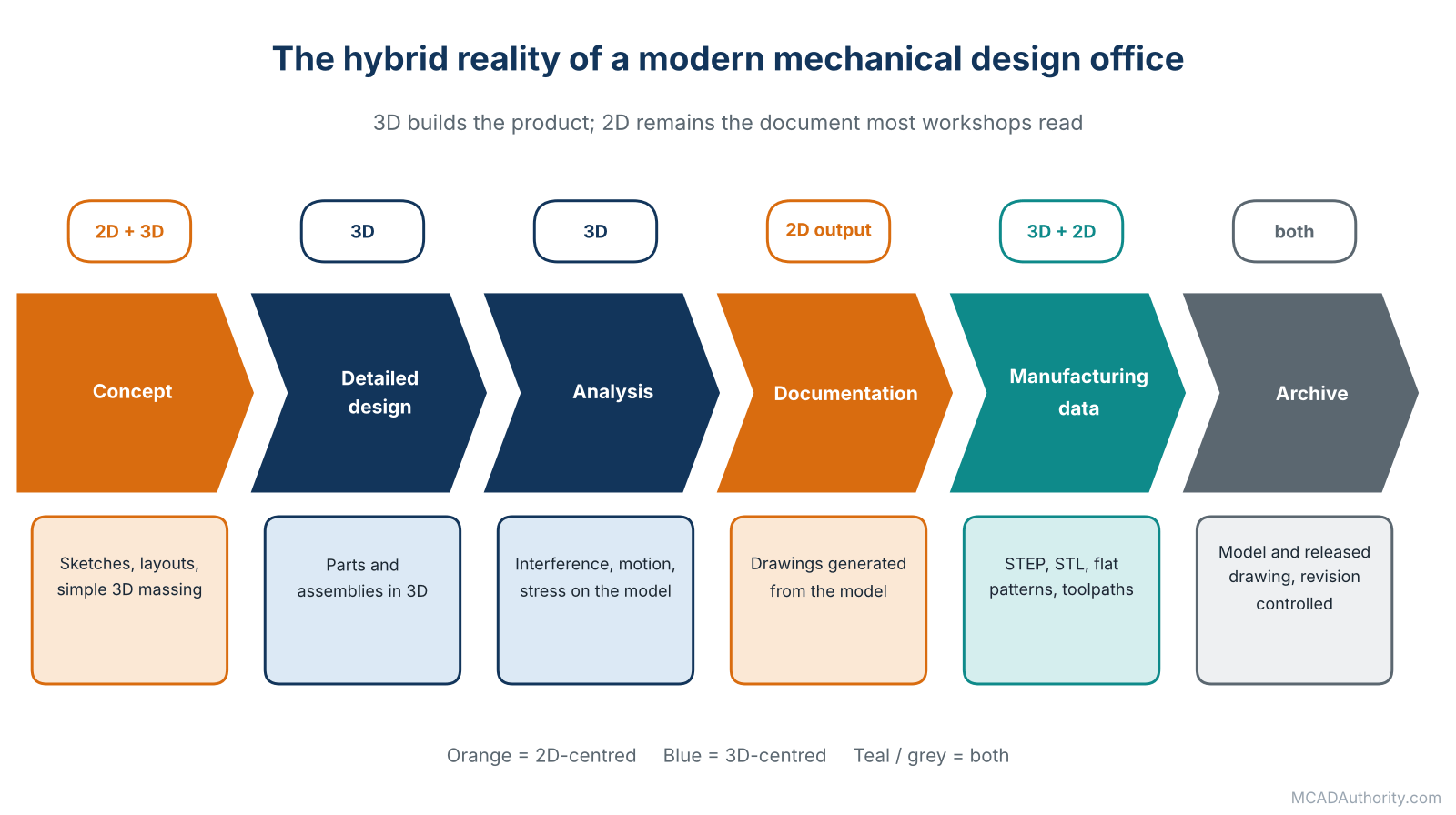
Figure 3. In a modern office 3D builds the product and 2D remains the document many workshops read.
The tools I use in training reflect this reality. In Autodesk’s ecosystem, for example, Inventor and Fusion produce 3D models and automated drawings, while AutoCAD and AutoCAD Mechanical remain strong at 2D layout and legacy drawings, and they all exchange data using DWG and neutral formats. The details of exchange are covered in Mechanical CAD File Formats: A Complete Guide.
The lesson is that both skills belong to the same professional. The best designers I have hired could think in 3D and read a messy 2D drawing at the same time.
Do You Still Need to Learn 2D If You Learn 3D?
Yes, and here is why, in the words I give my students.
- You will read drawings your whole career. Suppliers, customers and older archives all send them.
- Drawing views teach you how objects are described. Understanding projection, sections and dimensioning makes you a better modeler.
- Your 3D model must eventually become a 2D document. If you do not understand drawing conventions, your model will produce poor drawings.
- Standards still speak 2D. ASME and ISO conventions for tolerances, symbols and views are the language of manufacturing. For a start, see Geometric Dimensioning and Tolerancing (GD&T): A Complete Guide.
- It trains the eye. Drafting builds spatial reasoning.
My own recommendation for a beginner: spend the first few weeks learning to read and sketch simple orthographic views by hand, then move to 3D modeling. It will accelerate everything else.
Moving a Team From 2D to 3D: What Actually Works
I have supervised this transition several times, and the successful ones follow the same pattern.
Start with a pilot
Pick a real but non-critical project. Train two or three motivated people. Let them make mistakes where the cost is low.
Build standards early
Create templates, naming rules, material lists and drawing standards before the whole team starts. If you wait, you will build bad habits at scale. Mechanical CAD Standards: A Complete Guide provides the framework.
Do not convert everything
Resist the temptation to remodel your entire archive. Model what you revise or reuse. Keep the rest as released 2D documents.
Respect the drafters
Experienced drafters understand manufacturing and documentation at a level that software cannot replace. Their knowledge becomes the foundation for quality 3D models and clean drawings. The best 3D designers I know were drafters first.
Invest in training
Professional training pays for itself. Self-taught designers often develop habits that cause problems when files are passed on or edited.
Plan for the dip
Productivity usually drops during the first weeks. Management must expect it and support it. Judge results after six months, not six days.
Set up data management
As soon as multiple people work on shared assemblies, you need controlled storage and versioning. See Product Data Management (PDM): A Complete Guide.
A Warning About “Extruding” Old Drawings
One shortcut I see constantly is the idea of importing old 2D drawings and extruding them into 3D to get models fast. It can work for very simple parts, but it has traps:
- The 2D geometry may contain small gaps, overlaps or duplicate lines that make clean solids impossible.
- Dimensions in old drawings may not match the actual geometry.
- The resulting model has no design intent, only shape. Editing it later is painful.
- Complex parts need careful rebuilding.
For simple components, importing and rebuilding is a decent starting point. For anything critical, model from scratch with intent, using the old drawing as reference.
Common Myths I Hear in Training Rooms
- “3D is only for big companies.” Today, subscription and cloud tools put it within reach of one-person shops.
- “2D is faster for everything.” For a single simple part, perhaps. Across a product’s lifetime, rarely.
- “If I model it in 3D, I no longer need drawings.” Not yet. Drawings remain the standard for manufacturing communication in most industries.
- “3D means I can ignore tolerances.” A model with perfect dimensions does not describe acceptable variation. Tolerances remain essential.
- “Anyone can learn 3D in a weekend.” The buttons, perhaps. The modeling strategy takes much longer.
- “3D models are always right.” A model is only as good as the person who made it. Always verify.
Practical Advice for Different Readers
If you are a student: learn to sketch and read drawings first, then build 3D skills seriously. Your portfolio should show both.
If you are a working drafter: you are better positioned than you think. Your knowledge of manufacturing and standards is the hardest part. Add solid modeling and you become very valuable. A good next step is How to Become a Mechanical CAD Designer.
If you are a manager: measure the cost of rework, errors and slow changes in your current process. That is the business case for 3D, not the glamour of the software.
If you run a small workshop: keep 2D where it is efficient and adopt 3D where it removes errors or opens new markets.
Final Thoughts
That drafter who whispered in the training room did, in the end, become one of my best 3D designers. It took him a few months to stop thinking about “views” and start thinking about “the part”. Once he did, he told me something I have never forgotten: “I finally understood that I was never drawing lines. I was always describing an object. Now I can describe it directly.”
That is the truth underneath the whole 2D versus 3D debate. 2D describes an object indirectly, through pictures. 3D describes it directly, and then produces the pictures when needed. Both are useful, but the object is what matters.
Where to go next: continue with How Mechanical CAD Is Used in Modern Product Development to see where these models fit into the real life of a product, and then explore Parametric vs. Direct Modeling: Which Approach Is Better? to understand how 3D models are structured.