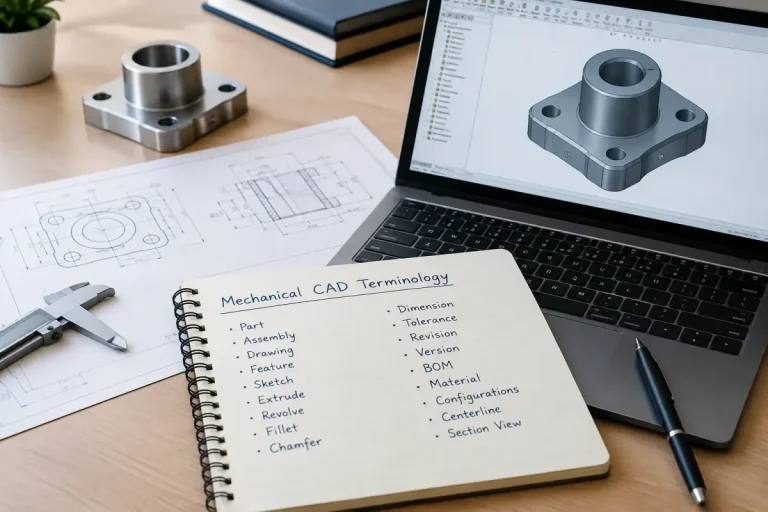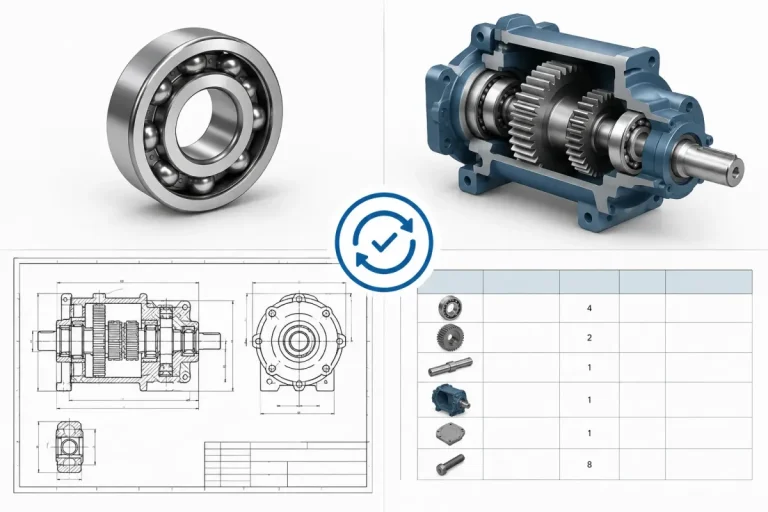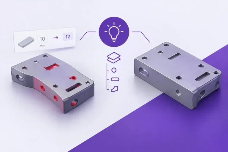

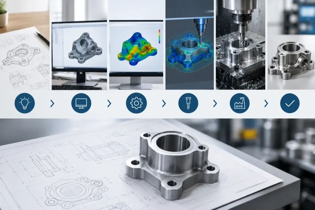

When I take over a design department, the first thing I ask for is not the software list, the license count or the project backlog. I ask a simple question: “Show me how a job travels from the first request to the finished part.” In well-run offices, someone can answer it in five minutes with a clear sequence. In struggling offices, I get five different answers from five different people, and every one of them includes the phrase “well, it depends”.
That difference, a shared, understood workflow, explains more about productivity and quality than any software choice I have ever seen. Two teams can use the same CAD system and get completely different results, because one works to a sequence that prevents errors and the other improvises every project from scratch.
This guide describes the complete Mechanical CAD workflow, from the first customer request to the production floor and beyond. I will walk you through each stage, what happens in it, what you produce, what to check before moving on, and where projects usually go wrong. The structure applies whether you design industrial machines, consumer products, tooling or medical devices, and whether your tool is Autodesk Inventor, Fusion, SOLIDWORKS, Creo or something else. If you have not yet read What Is Mechanical CAD (MCAD)? A Complete Beginner’s Guide, it is a good starting point.
The Short Answer: The Workflow at a Glance
Here is the whole journey in one line:
Requirements → Setup → Concept → Architecture → Detailed Design → Integration
→ Virtual Validation → Design Review → Prototype & Test → Documentation & Release
→ Manufacturing Handoff → Change Management
And here is the same journey as a table, with the main output of each stage and the question you must be able to answer before moving on.
| # | Stage | Main output | Gate question |
|---|---|---|---|
| 1 | Requirements | Written specification | Do we all agree on what we are building? |
| 2 | Project setup | Folders, templates, vault, standards | Can the team work without stepping on each other? |
| 3 | Concept | Layouts, sketches, simple 3D | Which solution are we pursuing, and why? |
| 4 | Architecture | Assembly structure, interfaces, envelopes | Are the modules and their boundaries defined? |
| 5 | Detailed design | Parts with intent | Does each part do its job and can it be made? |
| 6 | Integration | Full assemblies | Does everything fit and move as intended? |
| 7 | Virtual validation | Checks, simulations, tolerance studies | Will it work before we build it? |
| 8 | Design review | Approved design, action list | Have independent eyes found what we missed? |
| 9 | Prototype and test | Physical results | What did reality teach us? |
| 10 | Documentation and release | Drawings, BOM, 3D data, released revision | Is the information complete and controlled? |
| 11 | Manufacturing handoff | Supplier and shop packages | Can others build it without calling us? |
| 12 | Change management | Controlled revisions | Do we know what changed, why and who approved? |
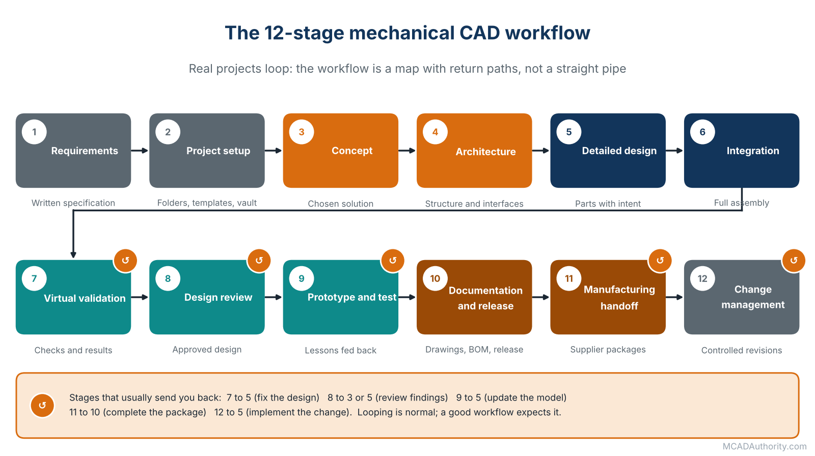
Figure 1. The twelve stages, and the places where projects normally loop back.
A word of honesty: real projects loop. You will go back from validation to detailed design, from prototype to concept, from manufacturing to documentation. That is normal, and a good workflow expects it. The workflow is not a straight pipe; it is a map with return paths.
Stage 1: Requirements, Know What You Are Building
Everything begins with understanding the need. I have never seen a project saved by skipping this stage, and I have seen many damaged by it.
What to collect
- Function: what the product must do, with numbers wherever possible (force, speed, capacity, cycle time, life).
- Interfaces: mounting, connections, existing equipment, utilities, software or electronics it must work with.
- Environment: temperature, humidity, dust, chemicals, outdoors, hygiene, vibration.
- Standards and regulations: machinery safety, medical, food, electrical, regional requirements.
- Constraints: size, weight, budget, schedule, available materials and manufacturing methods.
- Volume: one unit, a small series or mass production. This changes nearly every later decision.
- Lifecycle: service, maintenance, expected life, end of life.
What to produce
A written requirements document, even if it is one page. It should say what is mandatory, what is desirable and what is out of scope. Have the customer or project owner sign it.
Typical mistakes
- Accepting verbal requirements and discovering the disagreement at the first review.
- Mixing “must have” with “nice to have”.
- Ignoring service and maintenance until the product is finished.
My rule: if you cannot write the requirement, you do not understand it yet.
Stage 2: Project Setup, Prepare the Ground
This is the stage that undisciplined teams skip, and then pay for during the entire project. A good setup takes a few hours and prevents weeks of confusion.
Checklist
- Create the project structure. A clean folder layout, or a project in your data management system. In Autodesk Inventor this means a properly configured project file so that references resolve correctly; in cloud systems it means a project or hub with the right permissions.
- Set up data management. Decide where files live, who can edit what, and how versions are handled. See Product Data Management (PDM): A Complete Guide.
- Choose templates. Part, assembly and drawing templates with correct units, materials, title blocks and standards.
- Apply naming and numbering rules. Decide the pattern before the first file exists. See Mechanical CAD File Naming and Part Numbering Standards.
- Prepare libraries. Standard parts, purchased components, material lists.
- Define responsibilities. Who owns which assembly? Who reviews? Who releases?
- Agree on units and standards. Metric or imperial, ASME or ISO drawing conventions.
Why it matters
I once inherited a project where three designers had created three different part numbering schemes in the same assembly. We spent two weeks just renaming and re-linking files. All of it was avoidable. The principles are laid out in Mechanical CAD Standards: A Complete Guide.
Stage 3: Concept, Explore Before You Commit
Now design begins, but in a deliberately light way. The goal is to compare solutions, not to perfect one.
Activities
- Sketch layouts. Even rough hand sketches help.
- Build simple 3D massing models. Boxes and cylinders representing main components.
- Study mechanisms. Test motion with simplified geometry.
- Check feasibility. Can the main parts fit in the space? Can the motor reach the load?
- Compare options. Use a simple matrix: cost, complexity, risk, performance, manufacturability.
- Involve the people who will make and service it. A conversation in the workshop at this stage is worth ten reviews later.
Tools
Direct modeling is often excellent here, because you can push and pull shapes without worrying about history. See Parametric vs. Direct Modeling: Which Approach Is Better? For products with complex shapes, concept surfaces from industrial design may be imported or built; see Surface Modeling in Mechanical CAD: A Complete Guide.
Output
A chosen concept, with a short record of why alternatives were rejected. That record will save you arguments later.
Typical mistakes
- Over-detailing concepts. Do not model every fillet of a design that may be dropped.
- Falling in love with the first idea. Always compare at least two options.
- Ignoring manufacturing and cost until too late.
Stage 4: Architecture, Decide the Structure
Between concept and detailed design lies a stage many teams never name, though the good ones always do it. Architecture means deciding how the product is organized before you model the parts.
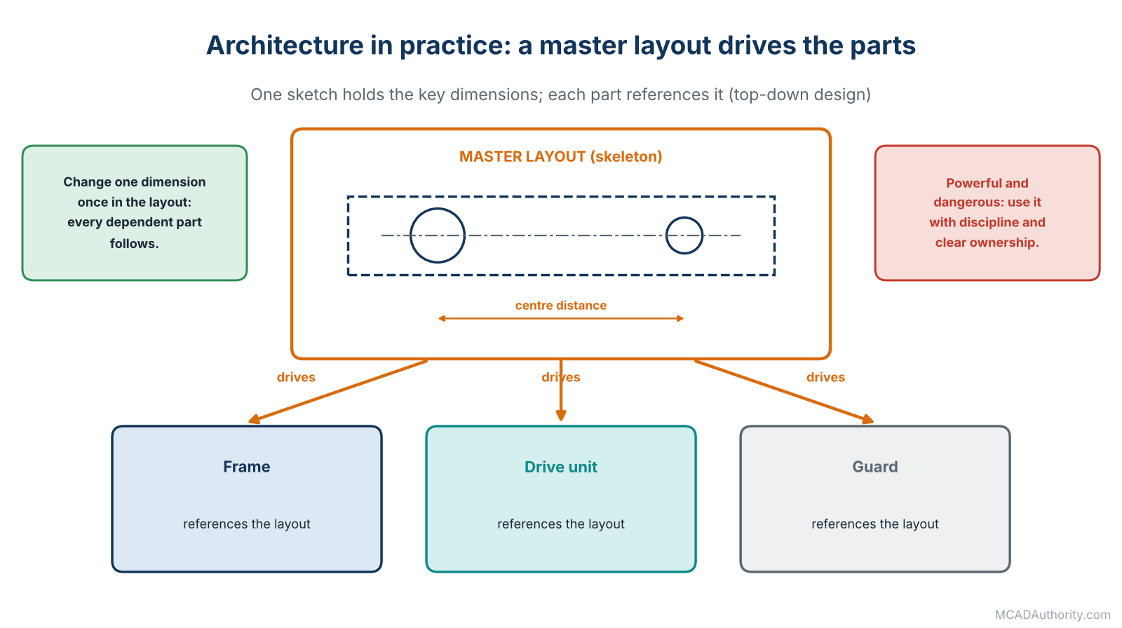
Figure 2. A master layout carries the key dimensions that drive the parts.
What to define
- Modules and subassemblies. What are the logical blocks: frame, drive, guarding, tooling, covers?
- Interfaces between modules. Where do they connect, and which dimensions are fixed?
- Envelopes. The maximum space each module may occupy.
- Master layout or skeleton. A sketch or simple model that carries the key dimensions and positions, from which parts are driven. See Skeleton Modeling and Master Layout Techniques.
- Make-or-buy decisions. Which components will you design and which will you purchase?
- Assembly strategy. Will you build bottom-up, top-down or a mix? See Bottom-Up vs. Top-Down Assembly Design.
- BOM structure. How should the product be broken down for purchasing, production and service? This is far easier to plan now than to correct later. See Understanding Parts, Assemblies, Drawings, and BOMs in MCAD.
- Responsibility split. Which designer owns which module, and how do they coordinate?
Why this stage pays
When several people work on one product, architecture is what keeps them from colliding. A well-defined interface lets two designers work in parallel without breaking each other’s models. Without it, every change in one part ripples through the others unpredictably.
Stage 5: Detailed Design, Build the Parts
Now the real modeling begins. Each part becomes a precise solid, built with intent, material and manufacturing logic.
The workflow for a single part
- Understand the function. What loads, motions and interfaces does this part have?
- Choose the material and process. Machined, cast, molded, sheet metal, printed, welded? This choice shapes everything. See Materials Selection Guide for Mechanical Design.
- Plan the model. Decide the base feature, the key dimensions and the order of operations before clicking.
- Start with the primary shape. The big, stable features first.
- Add functional features. Holes, pockets, bosses, slots, grooves that serve the product’s function.
- Add finishing features last. Fillets, chamfers, cosmetic details.
- Capture design intent. Use fully defined sketches, constraints and named parameters. See Understanding Design Intent in 3D Mechanical Modeling.
- Assign material and properties. So mass and appearance are correct.
- Check manufacturability. Radii, wall thickness, tool access, draft, tolerances.
- Save and check in properly. With clear naming and version control.
Using standard and purchased components
Insert fasteners, bearings and catalog items from libraries or supplier models. Mark them clearly as purchased components so they appear correctly in the BOM and are not drawn by mistake. See Managing Standard Parts and CAD Component Libraries.
Quality of the model matters
A model that looks right but is built poorly will cost far more in maintenance than it saved in creation. Guidance is available in Parametric 3D Modeling: A Complete Practical Guide and How to Build a Clean and Reliable CAD Feature Tree.
Typical mistakes
- Starting to model without understanding the part’s role.
- Under-defined sketches and fragile references.
- Ignoring how the part will be machined, molded or bent.
- Modeling threads and tiny details that add file weight but no information.
Stage 6: Integration, Bring It All Together
Individual parts are not a product. In this stage, you assemble them and discover whether the pieces truly belong together.
Activities
- Build subassemblies for each module.
- Combine subassemblies into the main assembly.
- Constrain components realistically, reflecting how they are located and how they move. See Understanding Assembly Constraints, Mates, and Joints and Assembly Modeling in Mechanical CAD: A Complete Guide.
- Add fasteners and standard components, with correct sizes and positions.
- Check interference and clearance. Automatic detection will reveal collisions you never saw.
- Test moving parts through their full range.
- Review accessibility. Can tools reach the bolts? Can parts be removed for service?
- Manage performance. Use simplified representations or lightweight modes for large assemblies. See How to Create and Manage Large CAD Assemblies.
Output
A complete, constrained, checked digital product. Think of it as the first time the machine “exists” as a whole.
Typical mistakes
- Waiting until all parts are finished before assembling anything. Assemble early and often.
- Fixing parts in space instead of constraining them.
- Ignoring small interferences because “it is only 0.2 mm”.
Stage 7: Virtual Validation, Test It Before You Build It
This is where modern workflow earns its keep. You can find a surprising number of problems without cutting any metal.
Validation activities
| Check | What it reveals |
|---|---|
| Interference and clearance | Collisions, tight gaps, assembly problems |
| Motion and kinematics | Range of movement, collisions in motion, speeds |
| Static stress analysis | Overstressed areas, excessive deformation |
| Thermal analysis | Hot spots, expansion problems |
| Vibration analysis | Resonance risks |
| Tolerance stack-up | Whether parts will still fit with realistic variations |
| Mass properties | Total weight, center of gravity, balance |
| Ergonomic and access studies | Usability and serviceability |
| Manufacturability review | Whether suppliers can build it at reasonable cost |
An introduction to analysis is given in Computer-Aided Engineering (CAE): A Complete Beginner’s Guide and Finite Element Analysis (FEA): Fundamentals for CAD Designers. Fit and variation are discussed in Tolerance Stack-Up Analysis for Mechanical Assemblies.
The honest limit
Simulation provides guidance, not guarantees. Results depend on assumptions: loads, supports, material data, mesh quality. I always insist that important simulations are checked against hand calculations or physical tests. See How to Validate Simulation Results Before Manufacturing.
Output
A list of validated points and a list of issues to fix. Loop back to design where needed.
Stage 8: Design Review, Fresh Eyes Find What You Cannot
No matter how careful you are, you have blind spots. A formal review is the cheapest quality control in engineering.
Who should attend
- The designer or design team.
- A senior engineer not involved in the details.
- Someone from manufacturing or the workshop.
- Quality or inspection, where relevant.
- Purchasing or supply chain for cost and availability questions.
- Service or maintenance, for products that will be repaired.
What to review
- Requirements: is each one met?
- Function and performance: simulations and calculations.
- Manufacturability and cost.
- Safety and compliance.
- Assembly and service.
- Model quality: structure, naming, intent.
- Drawing and BOM completeness.
A good checklist keeps reviews efficient. See Engineering Design Reviews: Procedures and Best Practices and Mechanical CAD Model Review and Quality Assurance Checklist.
Output
An approved design, or a list of actions with owners and dates. Never skip this stage because of schedule pressure. The review you skip is the one that would have caught the expensive error.
Stage 9: Prototype and Test, Reality Checks the Model
For many products, a physical prototype is the moment of truth, even in a fully digital workflow.
Prototype methods
- 3D printing for fast form and fit models. See How to Prepare Mechanical CAD Models for 3D Printing.
- CNC machining for functional parts in real materials.
- Sheet metal or laser-cut parts from flat patterns.
- Mock-ups and test rigs designed in CAD and built in the workshop.
Testing
Test what matters: performance, strength, noise, temperature, life, ease of assembly. Record the results, and feed them back into the model. A prototype that reveals a problem is a success, not a failure.
The feedback loop
Update the models with what you learned. If a hole had to be enlarged in the workshop, the CAD model must be corrected too. Otherwise your next release will repeat the problem. I have seen this cause the same error on three consecutive production batches.
Stage 10: Documentation and Release, Make It Official
When the design is stable, you create the formal documentation that production and suppliers will rely on.
What to produce
- Manufacturing drawings for each part to be made, with views, dimensions, tolerances, materials, finishes and notes. See Mechanical Engineering Drawings: A Complete Guide and How to Create Manufacturing Drawings from 3D CAD Models.
- Geometric tolerancing where function demands it. See Geometric Dimensioning and Tolerancing (GD&T): A Complete Guide.
- Assembly drawings and exploded views for production and service.
- Bills of materials, structured for the readers who will use them: purchasing, production, service. See Bill of Materials (BOM) Management in Mechanical CAD.
- 3D data for suppliers and machines. STEP and other formats, chosen carefully. See Mechanical CAD File Formats: A Complete Guide.
- Model-based annotations, if your company uses them. See Model-Based Definition (MBD) and 3D Product Manufacturing Information (PMI).
- Supporting documents. Specifications, test procedures, assembly instructions, certificates.
Release process
- Check everything. Drawings match models, BOM matches assembly, titles and revisions are correct.
- Approve. Per your company’s rules.
- Release in the data management system. The released version becomes read-only and formally issued.
- Notify. Purchasing, production, quality.
Typical mistakes
- Releasing drawings with missing materials or finishes.
- Mismatched revisions between drawing, model and BOM.
- Exporting STEP files from the wrong state of the assembly.
- Treating release as paperwork rather than a quality gate.
Stage 11: Manufacturing Handoff, Make Sure Others Can Build It
A design is only as good as the information that reaches the person who makes it. This stage is about clean, complete communication.
Packages for different processes
- Machined parts: drawing and 3D model, with clear datums, tolerances and surface finishes. Programmers will generate toolpaths from the model. See CAD to CAM: Understanding the Complete Manufacturing Workflow and How to Prepare CAD Models for CNC Machining.
- Sheet metal parts: drawing, flat pattern, bend table, material and finish. See Sheet Metal Design in 3D CAD: A Complete Guide.
- Welded structures: drawings with weld symbols, cut lists and assembly sequences. See Weldment Design and Modeling in Mechanical CAD.
- Castings and molded parts: drawings with draft, parting lines, shrinkage notes, tooling data.
- Additive parts: orientation, supports, material and post-processing.
- Purchased components: specification and supplier reference.
- Assembly instructions: order, torque values, special tools, inspection points.
For a complete list of what to include, see How to Prepare a Mechanical Design Package for Suppliers.
Support during production
Stay reachable. The first production run always raises questions. Respond quickly, record each answer, and update documents if the answer reveals a gap. Treat the first batch as a final validation.
Feedback to design
Ask the workshop: what was difficult, what could be improved, what would you change? Their answers are gold for the next project. This is the heart of Design for Manufacturing (DFM) and Design for Assembly (DFA): A Complete Guide.
Stage 12: Change Management, The Work Never Really Ends
After release, changes will come: customers request modifications, suppliers change components, production finds improvements, quality finds defects. A disciplined process keeps these changes under control.
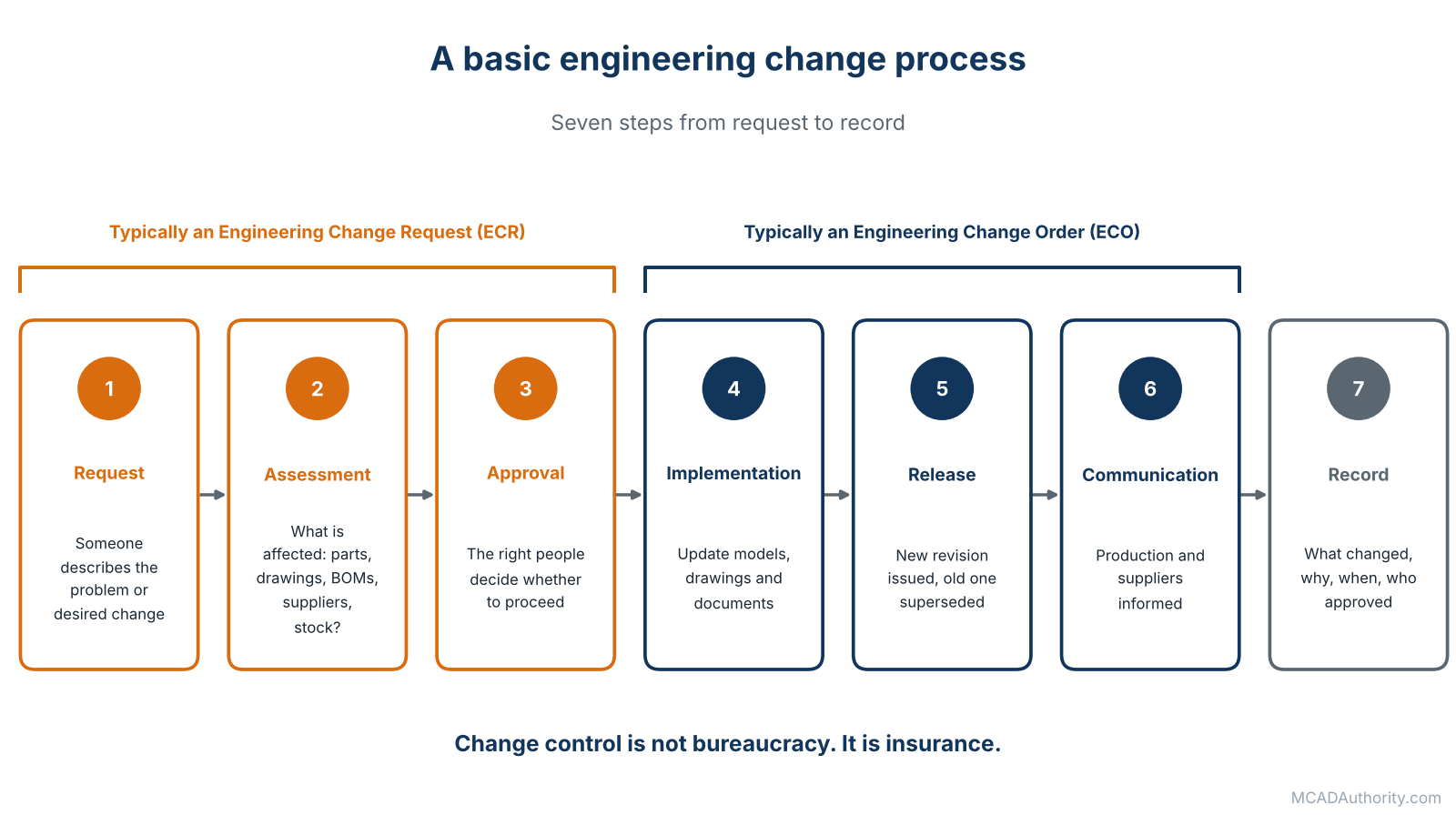
Figure 3. A basic engineering change process.
A basic change process
- Request: someone describes the problem or the desired change.
- Assessment: what is affected: parts, drawings, BOMs, suppliers, inventory, certifications?
- Approval: the right people decide whether to proceed.
- Implementation: update the models, drawings and documents.
- Release: new revision issued, old revision superseded.
- Communication: all affected parties informed, including production and suppliers.
- Record: what changed, why, when and who approved.
See Engineering Change Requests (ECR) and Engineering Change Orders (ECO) and CAD Version Control vs. Revision Control Explained.
Why it matters
I have seen products built to the wrong revision because someone updated a drawing but not the BOM. I have seen thousands of euros of material scrapped because a supplier worked from an obsolete file. Change control is not bureaucracy; it is insurance.
Adapting the Workflow to Your Situation
The twelve stages are a framework, not a rigid procedure. Here is how I adapt it.
One-person shop or freelancer
Compress the stages, but do not skip them. Write down your requirements, use a consistent folder structure, run your own checklist before release, and keep revision records. The discipline is the same, only the paperwork is lighter.
Small engineering team
Use light documentation, a shared vault or cloud project, templates and a short design review. Appoint one person as the standards owner.
Large company
Formal gates, defined roles, PDM and PLM integration, multi-site collaboration, and strict change control. The danger here is bureaucracy that slows everything, so keep the process proportional to the risk.
Custom machinery (one-offs)
Standard modules and a strong library accelerate work. Configure and adapt rather than redesign. Automation can pay off here. See Mechanical CAD Automation: A Complete Guide.
Mass-produced products
Heavy emphasis on DFM, tooling, tolerance analysis and validation, because errors multiply across thousands of units.
Work from customer-supplied models
You receive 3D data and must adapt or build on it. Check the data carefully, expect imported geometry issues, and agree on formats and responsibilities. See Repairing Imported CAD Models: Common Problems and Solutions.
Roles in the Workflow
Titles vary, but these responsibilities appear in every well-run team.
- Project owner / engineer: defines requirements, makes major decisions, owns the schedule.
- Mechanical designer: builds models, assemblies and drawings.
- CAD manager: maintains standards, templates, libraries and software environment.
- Analyst or simulation engineer: validates designs.
- Reviewer: independent technical check.
- Data manager or administrator: controls release and revisions.
- Manufacturing engineer or supplier contact: ensures producibility.
In small teams, one person may hold several roles. What matters is that each responsibility is clearly assigned, not that it has its own job title. For career context, see How to Become a Mechanical CAD Designer.
Where Workflows Break Down
After reviewing many struggling projects, I find the same bottlenecks again and again.
| Symptom | Usual cause | Remedy |
|---|---|---|
| Late surprises in assembly | Assemblies built too late | Integrate early and check often |
| Repeated rework of drawings | Weak models or late changes | Better model quality, change control |
| Wrong revision used in production | Poor release discipline | Controlled release in PDM |
| Designers waiting for each other | No clear architecture or interfaces | Define modules and ownership early |
| Parts that are hard to make | Manufacturing consulted too late | Involve the workshop from the concept stage |
| Models no one can edit | No standards, no intent | Templates, reviews, training |
| Endless meetings | Unclear requirements | Written specification and gates |
| Everyone using different methods | No shared workflow | Document and teach the process |
Most of these have nothing to do with the CAD software. They are process problems that software can reveal but not solve. If your troubles are more technical, Mechanical CAD Troubleshooting: A Complete Guide helps with the software side.
Measuring Whether Your Workflow Works
You cannot improve what you do not observe. A few simple measures, tracked over time, tell you a great deal.
- Design-to-release time for typical jobs.
- Number of drawing revisions after release (a high number indicates upstream problems).
- Errors found in production that originated in design.
- Rework hours per project.
- First-time fit rate of prototypes.
- Time lost searching for files or resolving version confusion.
- Review findings per project, and their severity.
Do not turn this into a surveillance system. Use the numbers to find friction, then discuss it with the team.
Building Your Own Workflow Document
I encourage every team to write a short, living document describing its own workflow. Mine usually includes:
- The stages your company actually uses, with names everyone recognizes.
- Inputs and outputs for each stage.
- Responsibilities for each role.
- Checklists for gates: setup, review, release.
- Standards references: templates, naming, drawing standards.
- Tool instructions: where files live, how to check in, how to release.
- Escalation paths: who decides when there is a conflict.
- A change log for the workflow itself.
Two pages are better than twenty. A short document that people actually read will always beat a manual that sits in a drawer. For the structure of such a document, see Building a Mechanical CAD Standards Manual for Engineering Teams.
A Compact Checklist You Can Print
Before leaving each stage, ask:
- Requirements: Is it written, agreed and signed?
- Setup: Are templates, naming and storage defined?
- Concept: Did we compare options and record the choice?
- Architecture: Are modules, interfaces and ownership clear?
- Detailed design: Are parts built with intent and manufacturability in mind?
- Integration: Is the assembly constrained, clash-free and structured for the BOM?
- Validation: Have we tested what matters, and are the results documented?
- Review: Did independent eyes check the design?
- Prototype: Did we feed the lessons back into the models?
- Release: Do drawings, models and BOMs agree, and is the revision controlled?
- Handoff: Can suppliers and the workshop build it without guessing?
- Change: Is every modification requested, approved, recorded and communicated?
Final Thoughts
After more than thirty years, I have come to believe that a good workflow is a form of respect: for your colleagues, who should not have to guess what you meant; for your suppliers, who deserve clear information; and for your customers, who trust you to deliver something that works. It is also a form of self-defense, because the discipline you apply today is what protects you from the late-night emergency six months from now.
You do not need a perfect workflow. You need one that is written, shared and improved a little with every project. Start with the twelve stages above, adapt them to your reality, and keep what works.
Where to go next: go deeper on the parts of the workflow that interest you most. Mechanical Product Development: From Concept to Production covers the management side, Assembly Modeling in Mechanical CAD: A Complete Guide the integration stage, and Mechanical Engineering Drawings: A Complete Guide the documentation stage. If you are building a team, start with Mechanical CAD Standards: A Complete Guide.