
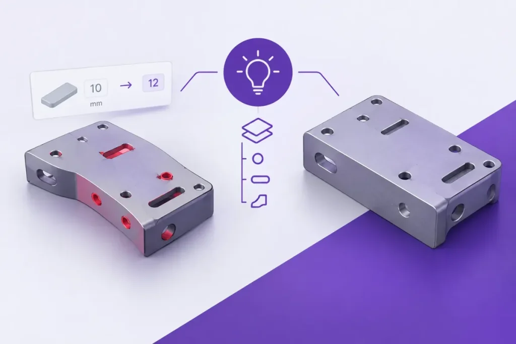

Some years ago a colleague sent me a model and a polite request: “Could you just change the plate thickness from 10 to 12 mm?” The part was a simple mounting plate with a pattern of holes, two slots and a handful of fillets. On screen it looked perfect. I changed one number, pressed enter, and watched the plate fold in on itself. The holes jumped to the wrong side, a slot disappeared and three features turned red.
Nothing was wrong with the software. Nothing was wrong with my colleague’s skill, either; he was a gifted modeler. What was missing was something you cannot see in a screenshot: design intent. His model captured what the plate looked like today. It had no memory of how the plate was supposed to behave when something changed.
If I had to name the single concept that separates a professional MCAD model from an amateur one, it would be this. Not the number of features, not the elegance of the surfaces, not the speed of the modeling. Intent. In this guide I will show you what design intent really means, where it lives inside a model, how to build it in from the start and how to test whether you have succeeded.
If you are new to the field, What Is Mechanical CAD (MCAD)? A Complete Beginner’s Guide and Parametric vs. Direct Modeling: Which Approach Is Better? will give you the background.
The Short Answer
Design intent is the set of rules, relationships and decisions that define how a model should behave when it is changed, and why it is built the way it is.
A model with good design intent:
- Updates predictably when you edit a dimension.
- Preserves what matters (a hole stays centered, a wall stays uniform, a fit stays a fit).
- Can be understood by another person without a long explanation.
- Can be reused for variants and future products.
A model without it is just a frozen shape: correct today, fragile tomorrow.
Three Kinds of Intent You Must Capture
When I teach this subject, I divide intent into three layers. A serious designer thinks about all three.
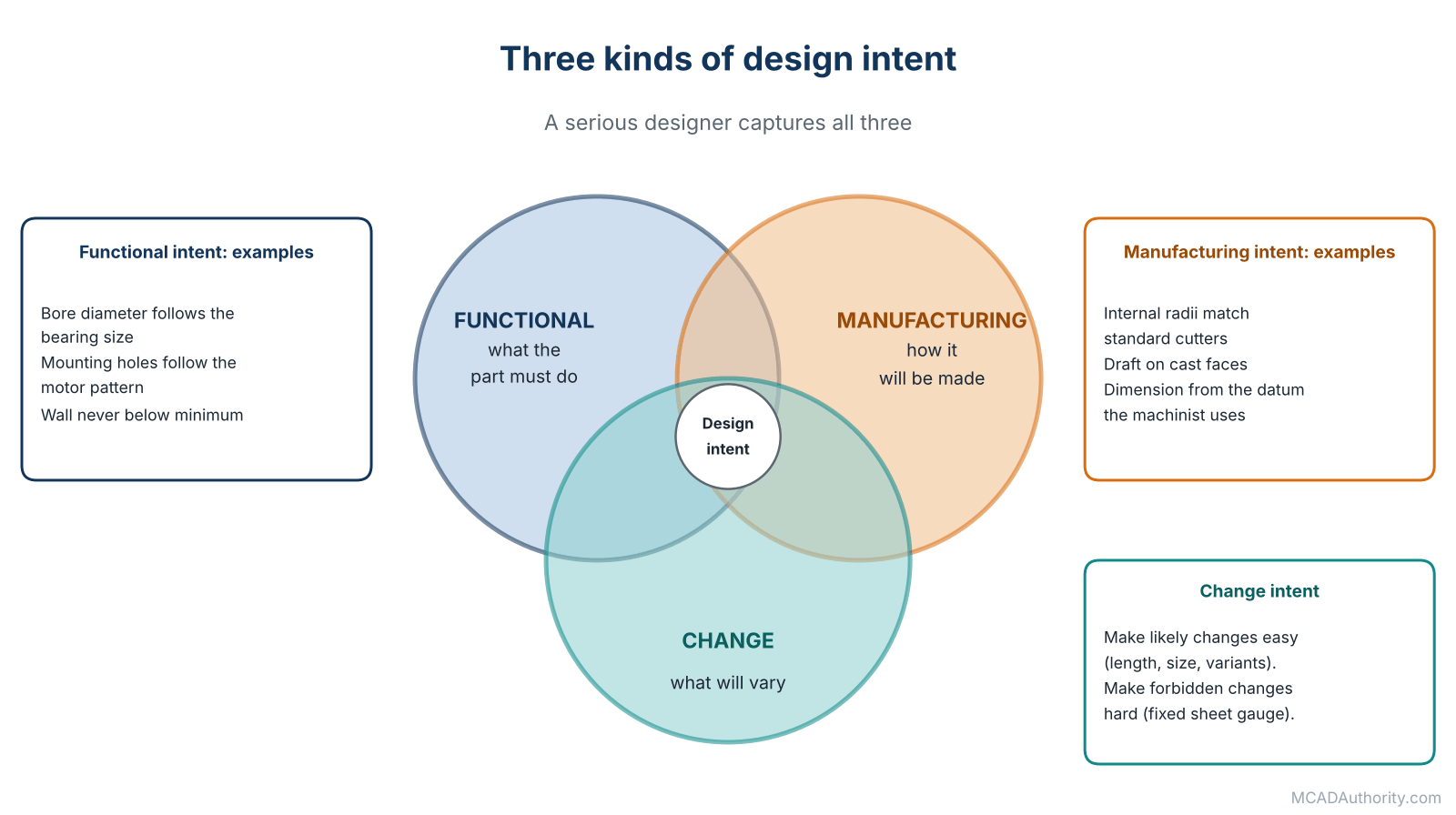
Figure 1. Functional, manufacturing and change intent overlap in every good model.
1. Functional intent: what the part must do
This is the engineering reason behind the geometry. Examples:
- This bore must accept a bearing, so its diameter and depth are controlled by the bearing size.
- These two mounting holes must align with the motor flange, so they are positioned from the motor’s pattern.
- This wall must be at least 3 mm to carry the load.
- This pocket must clear the moving arm by a minimum gap.
Functional intent is the most valuable kind, because it protects the product’s performance.
2. Manufacturing intent: how the part will be made
The model must reflect real production constraints:
- The part will be milled, so internal corner radii must match standard cutter sizes.
- The part is a casting, so draft angles must exist on vertical faces.
- The part is cut from sheet, so thickness and bend radii follow the material table.
- The machinist will measure from this edge, so dimensions start there.
Manufacturing intent is why a good drawing is easy to inspect and a bad one generates a hundred phone calls. It connects naturally to Design for Manufacturing (DFM) and Design for Assembly (DFA): A Complete Guide.
3. Change intent: what is likely to vary
This one is often overlooked. It asks: what will probably change in the future, and what must never change? A bracket that exists in three lengths needs length to be a clear, easy parameter. A housing that will be scaled for different motors needs its mounting pattern tied to motor size. A thickness that is fixed by a standard sheet gauge should not be easily editable.
Capturing change intent means making the likely changes easy and the forbidden changes hard.
Where Design Intent Lives Inside a Model
Intent is not a single setting. It is stored in many small decisions. Here is the complete list I walk new designers through.
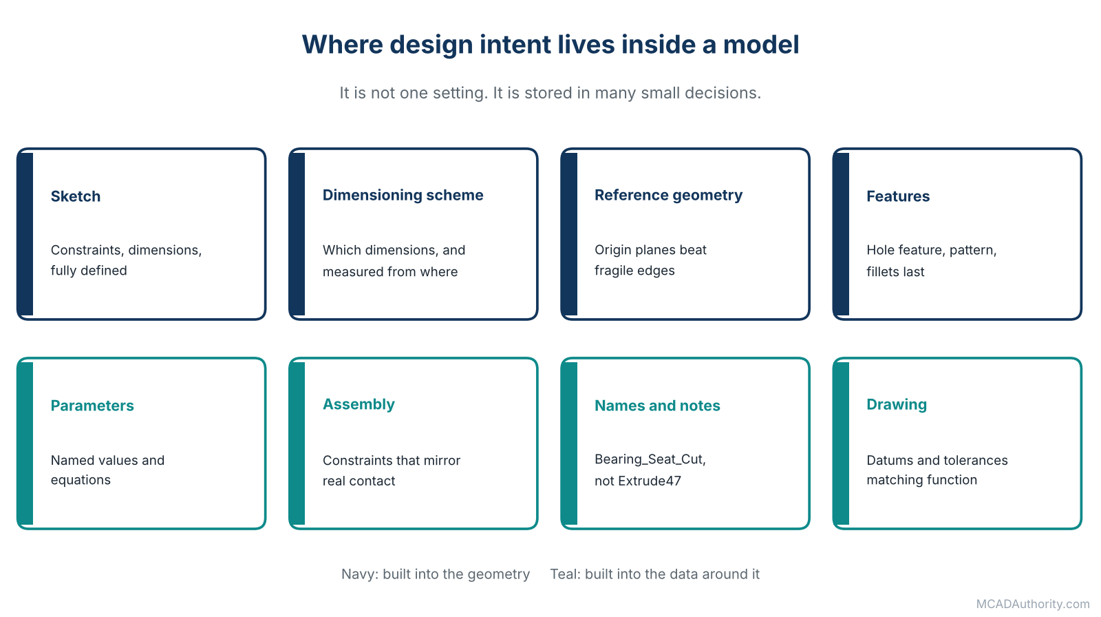
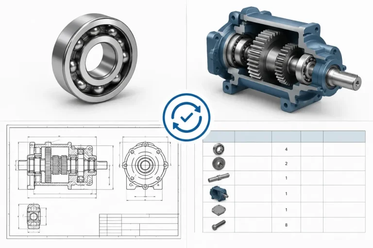
Figure 2. Intent is stored in many small decisions, not in one setting.
The sketch
- Constraints record geometric relationships: parallel, perpendicular, tangent, concentric, equal, symmetric.
- Dimensions record sizes and positions.
- Fully defined status means nothing is left to chance.
- Construction geometry (centerlines, helper circles) records the logic behind a profile.
The dimensioning scheme
Which dimensions you choose, and from where you measure them, is intent. Dimensioning a hole from the left edge says something different from dimensioning it from the center of the part. One of them is probably wrong for your situation.
The reference geometry
What your sketch is attached to matters. A sketch on an origin plane is stable. A sketch placed on the face created by a fillet is fragile, because if the fillet changes or disappears, the sketch loses its anchor.
The feature choice and order
Using a proper hole feature instead of a plain cut tells the software (and the next designer) that this is a hole, with a standard size and thread. Using a pattern instead of ten copied features states that these ten items are related. Applying fillets last records that they are finishing touches, not structural elements.
Parameters and equations
Named parameters and formulas turn hidden relationships into explicit rules. For example:
Wall_Thickness = 3 mm
Boss_Diameter = Hole_Diameter + 2 * Wall_Thickness
Pitch_Circle = Motor_Flange_PCD
Now the boss diameter cannot drift out of sync with the hole.
Assembly relationships
How you constrain parts in an assembly expresses how they work together. A shaft that is constrained to sit against a shoulder, not floated at an arbitrary position, records the real function. In a larger project, a master layout or skeleton can drive the positions of many parts, as discussed in Skeleton Modeling and Master Layout Techniques and Assembly Modeling in Mechanical CAD: A Complete Guide.
Names, notes and properties
Feature names, parameter names, material choices and notes explain the model to humans. A feature called Bearing_Seat_Cut carries meaning. A feature called Extrude47 carries none.
The drawing
Which dimensions you show, which datums you establish and which tolerances you apply on the drawing are intent too. If the model’s logic and the drawing’s logic disagree, the manufacturer will follow the drawing. See Mechanical Engineering Drawings: A Complete Guide and Geometric Dimensioning and Tolerancing (GD&T): A Complete Guide.
A Worked Example: The Mounting Plate
Let us return to the plate that folded. It is a rectangular plate, 120 by 80 mm, 10 mm thick, with four mounting holes and a central opening. Two designers model it. Both produce an identical shape. Here is how their intent differs.
| Aspect | Designer A (shape only) | Designer B (with intent) |
|---|---|---|
| Sketch origin | Rectangle drawn anywhere, with one corner at a random position | Rectangle centered on the origin with symmetry constraints |
| Hole positions | Four holes, each dimensioned separately from the same corner | One hole dimensioned, then mirrored twice, so the pattern is always symmetric |
| Hole size | Four separately drawn circles with typed diameters | One circle, with the others equal to it; or a hole feature with a defined size |
| Central opening | Dimensioned from one corner | Centered with a constraint; diameter linked to a named parameter |
| Fillets | Selected edge by edge, applied early in the tree | Corner fillets applied at the end, selected by feature |
| Thickness | A typed number in the extrude | A named parameter, Plate_Thickness |
| Names | Default names | Meaningful names |
| Sketch status | Partially defined, some lines free | Fully defined |
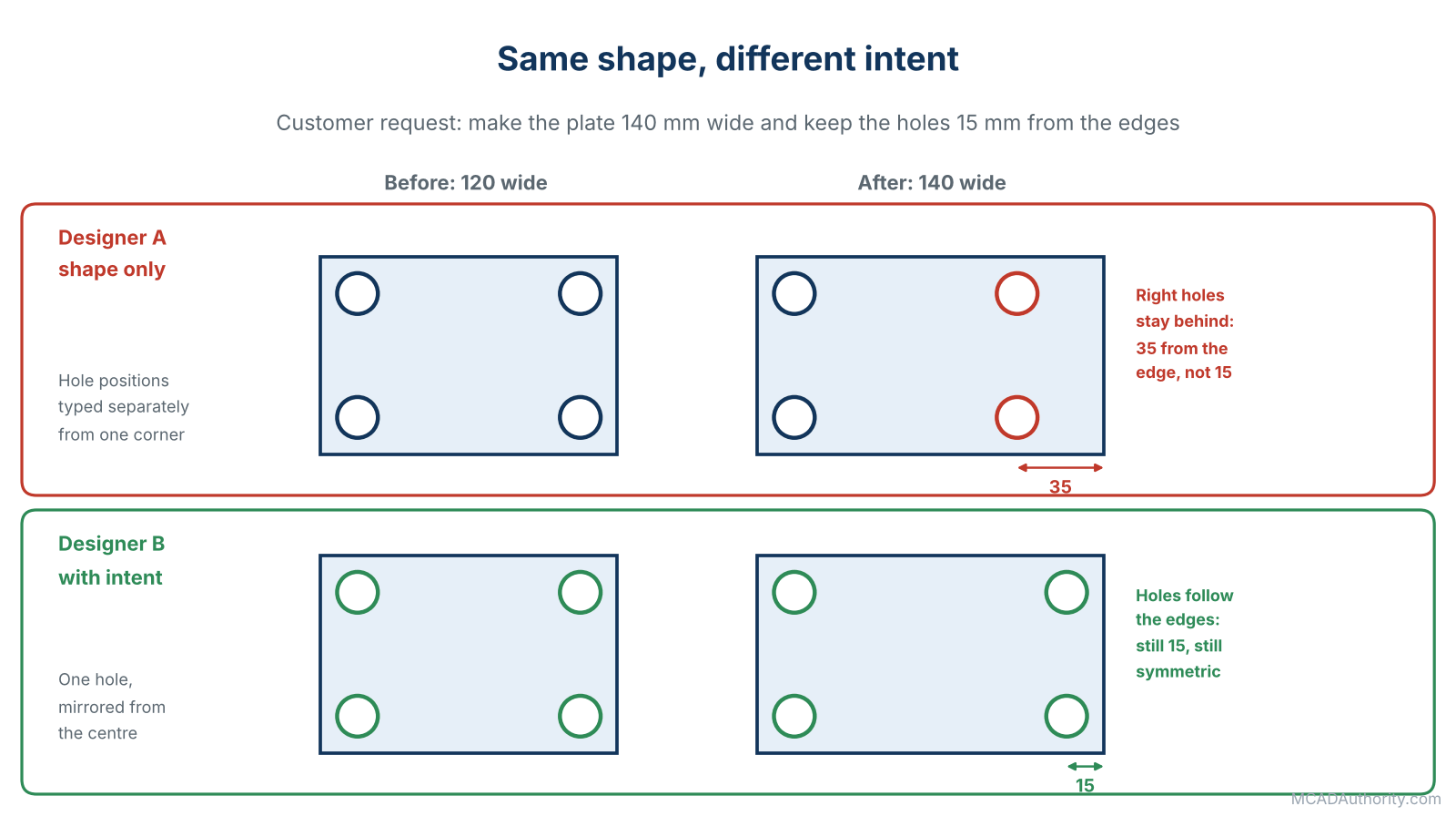
Figure 3. The same plate modeled two ways, before and after widening it.
Now the customer asks: “Make it 140 mm wide and keep the holes 15 mm from the edges.” Designer B edits one dimension and the holes follow, symmetrically, because the pattern is built on the plate’s center. Designer A must edit four holes individually and hope he remembers all four, and he must check the central opening manually.
Neither designer needed more time to build the first model. Only one of them saved time on every change afterward.
A Second Example: The Shaft
Consider a stepped shaft carrying two bearings and a gear. This example shows functional intent clearly.
- The bearing seats have diameters that come from the bearing’s bore. If the bearing changes, these diameters should change together.
- The shoulders that locate the bearings are positioned from a datum, perhaps the gear seat shoulder, because the machinist will turn the shaft and measure from that face.
- The snap ring grooves are placed at a distance from the shoulder defined by the ring supplier, not at an arbitrary position.
- Keyways are sized from the shaft diameter according to a standard.
- Chamfers and fillets at shoulders follow rules that avoid stress concentration.
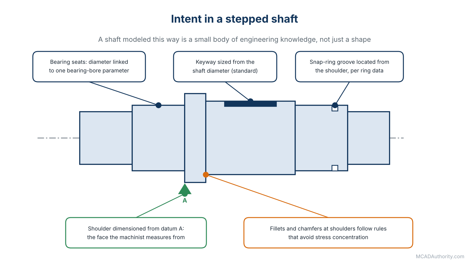
Figure 4. Design intent in a stepped shaft.
A shaft modeled this way is not merely a shape. It is a small body of engineering knowledge. Change the bearing and the right things follow. Hand the model to a colleague and she understands what the designer was thinking. Parts like this are discussed further in Shaft Design and Modeling in 3D CAD and Machine Elements: A Complete Guide for CAD Designers.
Building Intent Into Sketches
Most of the intent in a part lives in its first sketch, so it deserves special care. These are the habits I insist on.
- Start from the origin. Anchor the sketch to the origin or to a meaningful reference. Never leave it floating in space.
- Use symmetry when the part is symmetric. A centerline and a symmetric constraint say more than two equal dimensions.
- Use constraints before dimensions. Let relationships (equal, parallel, tangent, concentric) do as much work as possible, then add only the dimensions that matter.
- Dimension for function. Ask of each dimension: “Would I want to change this directly? Does this relate to a requirement?”
- Avoid redundant or conflicting dimensions. If the software complains about over-constraint, do not just make the dimension “driven” without thinking. Consider which one expresses the real intent.
- Keep sketches simple. One sketch, one purpose. Avoid cramming ten features into one complicated profile.
- Use construction geometry. Helper lines and circles record the logic behind the shape.
- Be careful with projected edges. Dimensioning to geometry projected from another feature creates a dependency. Do it deliberately, not by accident.
- Aim for fully defined. An under-defined sketch can move unpredictably when edited. When troubleshooting such problems, Resolving Overdefined and Underdefined Sketches will help.
Building Intent Into Features
Beyond sketches, the way you choose and order features carries meaning.
- Use specialized features. A hole feature, a thread feature or a shell feature communicates purpose. A generic extruded cut says only “material removed here”.
- Use patterns and mirrors. They record repetition and symmetry.
- Order features logically. Primary shape first, functional features next, cosmetic items last. How to Build a Clean and Reliable CAD Feature Tree offers a complete strategy.
- Choose references carefully. Anchor to stable geometry. If a feature is attached to another feature that may be edited or deleted, you create a weak link.
- Reuse rather than copy. If a feature appears in several parts, consider using shared definitions, libraries or derived parts.
- Avoid unnecessary features. Every feature is a future maintenance task.
- Use fillets and chamfers as finishing features, applied late so they do not block earlier edits.
Building Intent Into Assemblies
Intent does not stop at the part level. In assemblies it takes the form of relationships that mirror reality.
- Constrain parts the way they are actually located. A pin sits in a hole; a flange sits against a face; a shaft rests on a shoulder.
- Avoid fixing too many parts in space. Over-reliance on fixed positions hides real relationships.
- Use the same datums in the model as in the machine. If the machine frame is the reference, tie the sub-assemblies to it.
- Consider top-down relationships where one part’s geometry drives another’s. These are powerful and dangerous, so use them with discipline. See Bottom-Up vs. Top-Down Assembly Design.
- Flexible or adaptive behavior (where available) should be applied sparingly and documented, as it can make assemblies unpredictable.
- Use configurations to represent different states or sizes without duplicating files.
In my experience, assemblies built with sloppy constraints are among the most expensive messes a company can inherit. Everything looks fine until someone moves one part and the entire structure collapses.
Intent on the Drawing: Where It Meets the Machinist
A model with excellent intent can still produce a bad drawing, if the drawing communicates a different logic. Here is what I check.
- Datums on the drawing match functional datums on the part. The machinist and the inspector should be measuring from the same surfaces the designer used for function.
- Dimensions avoid chains that accumulate tolerance. Where precision matters, dimension from a common datum, not from feature to feature. See Tolerance Stack-Up Analysis for Mechanical Assemblies.
- Critical dimensions are visible and prioritized. Not hidden among a hundred trivial ones.
- Notes record requirements that geometry cannot show: material, finish, heat treatment, inspection.
- Tolerances reflect function and cost. Tight where required, general elsewhere. See Manufacturing Tolerances and Their Impact on Product Cost.
If the model and drawing tell different stories, the drawing wins, because that is what the shop reads. Make sure they tell the same one.
The “Change Test”: How to Check Your Intent Before Release
This is the simple procedure I make every designer follow before a model leaves their hands. It takes five minutes and has saved me countless hours.
- Change the overall size by 20 to 50 percent. Does the model still look right?
- Change the thickness or wall. Do dependent features still work?
- Change a hole diameter to a larger and smaller value. Do bosses and fillets adapt?
- Change the number of items in a pattern. Does the pattern stay inside the part?
- Move a key dimension to an extreme within its realistic range. Does anything fail?
- Suppress a major feature. Do later features remain stable, or do they cascade?
- Open the model as if you were someone else. Can you understand why each feature exists?
- Check the drawing. Do the views and dimensions update correctly?
If the model survives, you have probably captured the intent. If it breaks, the failure shows exactly where the intent was missing. Treat each failure as a lesson, not an annoyance.
Making Intent Explicit: Documentation Habits
Intent held only in a designer’s memory disappears when that person leaves. Good teams write it down, lightly but consistently.
- Name features, sketches and parameters descriptively.
- Use notes or comments in sketches and features where a relationship is non-obvious.
- Record key requirements in model properties or a short design note: loads, standards, reasons for critical dimensions.
- Use templates that include standard parameters, units and materials.
- Keep a short “design intent” statement for complex or critical parts: three or four lines explaining what controls what.
- Review models in the same way you review drawings. See Mechanical CAD Model Review and Quality Assurance Checklist.
- Teach it. Intent is a team culture, not an individual talent.
All of this belongs naturally within your department’s standards, as explained in Mechanical CAD Standards: A Complete Guide.
The Mistakes I See Most Often
- Modeling what it looks like, not how it works. The classic. Dimensions chosen because they were easy to type.
- Hard-coded numbers. The same value typed in three places. One day, only two of them change.
- Dimensioning to arbitrary edges. Especially edges produced by other features, creating invisible dependencies.
- Leaving sketches under-defined. “It looks right” is not a constraint.
- Over-constraining with unnecessary relationships. Locking the model so firmly that simple edits become impossible.
- Copying geometry instead of relating it. Duplicated features that should be linked.
- Ignoring manufacturing. Beautiful intent for a part that cannot be made.
- No documentation. Brilliant logic that no one else can read.
- Confusing intent with complexity. A model overloaded with formulas for changes that will never happen.
A Caution: Do Not Over-Engineer Your Models
There is an opposite danger that deserves honesty. I have also met designers who, after discovering intent, drive every dimension with equations and hide the logic behind layers of linked parameters. Their models are marvels of cleverness and nightmares to edit.
The goal is not to maximize intent. The goal is to capture the intent that matters:
- Capture relationships that protect function or fit.
- Capture changes you actually expect.
- Leave other things simple and explicit.
A good rule is to ask, for each relationship: Would someone be unhappy if this broke silently? If yes, encode it. If not, keep it simple.
Design Intent and Direct Modeling
Some readers will ask: “If I work with direct modeling, does intent still matter?” Yes, though it lives elsewhere. In a direct approach, intent is carried more by the designer’s discipline and documentation than by the software’s structure. You verify relationships manually, you annotate carefully and you accept that the model will not protect itself. That is a legitimate choice for short-lived or exploratory work, and a risky one for controlled products. The trade-offs are explored fully in Parametric vs. Direct Modeling: Which Approach Is Better?
Five Practice Exercises
To build the habit, try these on any MCAD system.
- The symmetric bracket. Model a bracket symmetric about a center plane, using only constraints and one half-dimension for each feature. Test it by changing its width.
- The flange. Create a round flange with a bolt circle. Drive the number of holes, bolt circle diameter and thickness from named parameters. Change each and verify.
- The enclosure. Model a box with a lid and uniform walls. Make the wall thickness a single parameter used everywhere.
- The shaft. Model a stepped shaft with two bearing seats whose diameters are linked to a single bearing bore value.
- The stranger’s model. Ask a colleague to give you a model you have never seen. Try to change it. Note where you struggled, and ask what intent was missing.
More structured practice is available in Mechanical CAD Practice Exercises for Beginners.
Final Thoughts
After all these years, I still remember the scrambled mounting plate, because it taught me something no manual had: a CAD model is a message to the future. The future reader may be a colleague, a customer, a supplier or yourself two years from now, with no memory of what you were thinking. A model without intent says only “this is what I made”. A model with intent says “this is what I meant, and here is how to change it safely.”
Take the extra minutes at the start. Define your sketches. Choose your references. Name your parameters. Run the change test. Those minutes are the best investment you will make in any design project.
Where to go next: read The Complete Mechanical CAD Workflow: From Concept to Manufacturing to see where design intent fits in the sequence of a real project, and Parametric 3D Modeling: A Complete Practical Guide for hands-on techniques.