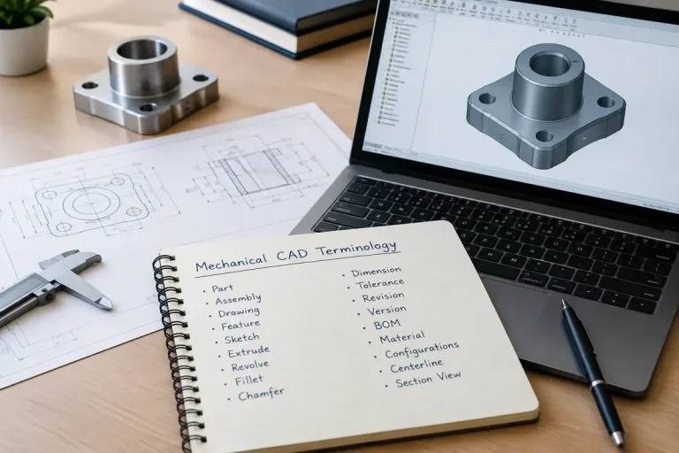



My first job in this profession started at a drafting board. I had a parallel rule, a set of technical pens, a bottle of erasing fluid and a supervisor who could spot a line that was 0.3 mm too thick from across the room. A single assembly drawing could take a week, and a late change from the customer meant redrawing the sheet. In the years since, I have moved from boards to 2D screens, from 2D screens to solid models, and from there to running CAD departments and training hundreds of designers on the software. Through all of that, one thing has stayed true: the tool is never the point, the thinking behind it is.
If you are reading this, you are probably at the start of that journey. Maybe you have just been told to “learn CAD” for a new job. Maybe you are a student, a machinist who wants to design instead of only make, or an inventor with a sketch on a napkin. Whatever your story, this guide will give you the full picture of Mechanical CAD, what it is, what it does, how it is organized and how to begin, in the plain language I use with my own trainees.
The Short Answer: What Is MCAD?
MCAD stands for Mechanical Computer-Aided Design. It is the use of specialized software to design, model, analyze and document mechanical products: parts, machines, mechanisms, tools, enclosures, frames and anything else that has to be physically made, assembled and made to work.
Three words in that definition deserve attention.
- Design. MCAD is not drawing software. You are not producing pictures; you are making decisions about shape, size, material, motion and fit.
- Mechanical. The objects you model obey physics. They have mass, they carry loads, they move, they wear, they heat up, and they have to be manufactured by real machines with real limits.
- Aided. The computer helps you, but it does not think for you. It calculates volumes, checks collisions, updates drawings and keeps everything consistent. The engineering judgment is still yours.
When people say “CAD”, they often mean any software used to draw with a computer. MCAD is the branch dedicated to mechanical products. In Mechanical CAD vs. General-Purpose CAD: Key Differences Explained I go deeper into how it differs from the broader family, but the simplest way to remember it is this: a general CAD tool draws, an MCAD tool engineers.
What MCAD Actually Produces
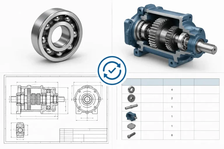
A beginner often imagines that the result of MCAD is a nice 3D picture on the screen. In a real company, the picture is the least valuable output. Here is what the work product really looks like:
- 3D part models. Each component, from a tiny pin to a large housing, built as a precise solid with defined dimensions, material and finish.
- Assemblies. Many parts positioned and constrained together so you can see how the product fits, moves and is put together.
- Manufacturing drawings. The 2D documents, usually generated from the 3D model, that tell a machinist, a sheet-metal shop or a supplier exactly what to make and how accurately.
- Bills of Materials (BOMs). The structured lists of every part, quantity, material and reference number in the product.
- Manufacturing data. Files that feed machines directly: STEP files for suppliers, STL files for 3D printers, flat patterns for laser cutters, toolpaths for CNC machines.
- Analysis results. Stress, deflection, heat, vibration and motion studies that tell you whether the design will work before you spend money on a prototype.
- Visual communication. Renderings, animations and exploded views used for sales, assembly instructions and service manuals.
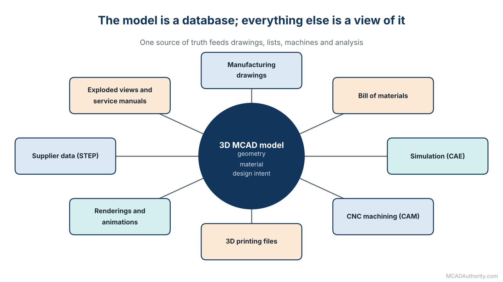
Figure 1. The model is the database; drawings, lists and files are views of it.
Notice how much of this is information, not graphics. That is the central idea of modern MCAD, and the first mental shift I try to give to every beginner: the model is a database of the product, and the drawings, lists and pictures are simply views of that database. I explore this relationship in Understanding Parts, Assemblies, Drawings, and BOMs in MCAD.
The Building Blocks of an MCAD Model
Whichever software you use, whether Autodesk Inventor, Fusion, SolidWorks, Creo, NX or another, the logic of building a model is remarkably similar. Learn it once and you can move between systems with a few weeks of adjustment, not years.
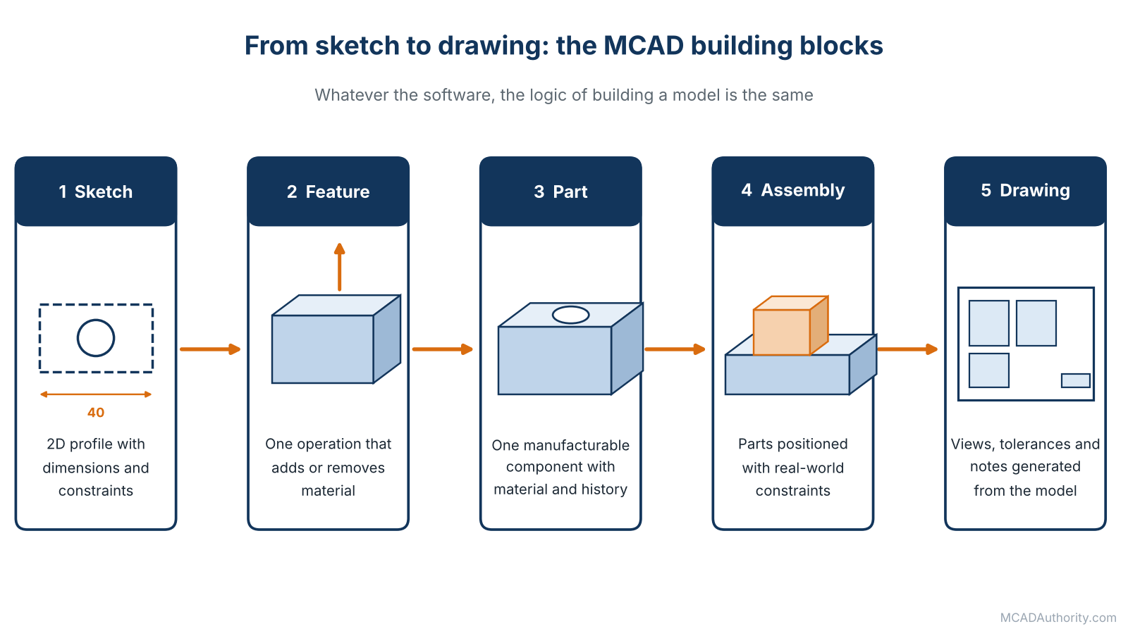
Figure 2. The chain every MCAD course teaches, whatever the software.
Sketches
Almost every 3D shape starts life as a 2D sketch drawn on a plane or on the face of another part: lines, arcs, circles and splines. But a sketch in MCAD is not just a drawing. It carries dimensions (this line is 40 mm long) and constraints (this line is parallel to that one, this circle is centered on that point). Constraints are how you tell the software the rules of the shape, not just its current appearance.
Features
A feature is a single modeling operation that adds or removes material. You extrude a sketch to give it thickness. You revolve a profile around an axis to make a shaft. You cut a hole, add a fillet to round an edge, create a shell to hollow out a casting. A part is the sum of its features, built one on top of another, like a recipe.
Parts
A part is a single manufacturable component made from a single material (or at least treated as such). A bracket, a shaft, a cover. The part file contains the geometry, the material, the mass properties and the history of how it was built.
Assemblies
An assembly brings parts together. You place a shaft into a bearing, a bearing into a housing, and you constrain them with relationships that mimic reality: this face touches that face, this axis aligns with that axis. A good assembly lets you check that things fit, that things move as intended, and that nothing collides. For a deep treatment, see Assembly Modeling in Mechanical CAD: A Complete Guide.
Drawings
A drawing is the formal documentation created from the part or assembly: views, sections, dimensions, tolerances, notes and title block. It is the contract between the designer and the manufacturer. Mechanical Engineering Drawings: A Complete Guide covers this in full.
If you remember this chain, sketch, feature, part, assembly, drawing, you already hold the skeleton of every MCAD course in the world.
Why Mechanical CAD Is Different From Drawing on Paper
When people ask me what the real advantage of MCAD is, I never answer “it’s faster”, although it often is. The real advantages are deeper.
The model knows things
A drawn line on paper knows nothing. A solid model knows its volume, its mass, its center of gravity, its moments of inertia. Give it a material such as steel or aluminum and it tells you the weight of the part to the gram. I have seen projects saved because a designer noticed, at the model stage, that a “simple” casting weighed three times what the specification allowed.
Change is cheap
On the drafting board, a change meant erasing and redrawing every affected view. In a parametric model, you change one dimension and the whole part, every related part and every drawing update together. That does not just save time; it changes how you design. You can try five variants in an afternoon instead of committing to the first idea.
Problems appear early
The cost of a mistake rises sharply as a project moves downstream. A wrong dimension found in the model costs minutes. The same error found after parts are machined costs money, time and often a difficult conversation with the customer. This is the old engineering rule of thumb: the earlier you find the problem, the cheaper it is. MCAD gives you the earliest possible warning, through interference checking, motion studies and simulation.
Everyone works from the same truth
When the model is the master, the machinist, the buyer, the quality inspector and the sales team all draw from one source. Version confusion, the classic plague of paper-era offices, does not disappear on its own, but with a proper data management system it becomes manageable.
A Short History (Because It Explains Today’s Software)
You do not need to memorize dates, but a quick tour explains why the tools look the way they do.
- Late 1950s and early 1960s. The first computer-aided design experiments appear, with systems such as Patrick Hanratty’s work on numerical control programming and Ivan Sutherland’s Sketchpad at MIT in 1963, which showed that a person could draw directly on a screen.
- 1970s. CAD lives on expensive mainframes inside aerospace and automotive giants. It is mostly 2D drafting and early surface modeling.
- 1982. Autodesk releases AutoCAD, bringing professional 2D drafting to ordinary personal computers. It democratized CAD, and it is the reason my generation of designers grew up on it.
- Late 1980s. Parametric, feature-based solid modeling arrives with Pro/ENGINEER. For the first time, a model could be driven by dimensions and relationships, not just geometry.
- 1990s. Solid modeling reaches the Windows desktop. SolidWorks appears in 1995, and Autodesk Inventor follows in 1999, making 3D mechanical design affordable for small and medium companies.
- 2000s. Simulation, data management and CAM move inside the CAD environment. Direct modeling and hybrid approaches emerge.
- 2010s. Cloud-based CAD such as Fusion and Onshape appears. Collaboration happens in a browser, and the idea of installing software on one machine begins to fade.
- Today. Generative design, automation and AI-assisted tools are entering daily practice. I discuss these cautiously in Artificial Intelligence in Mechanical CAD: Applications and Limitations.
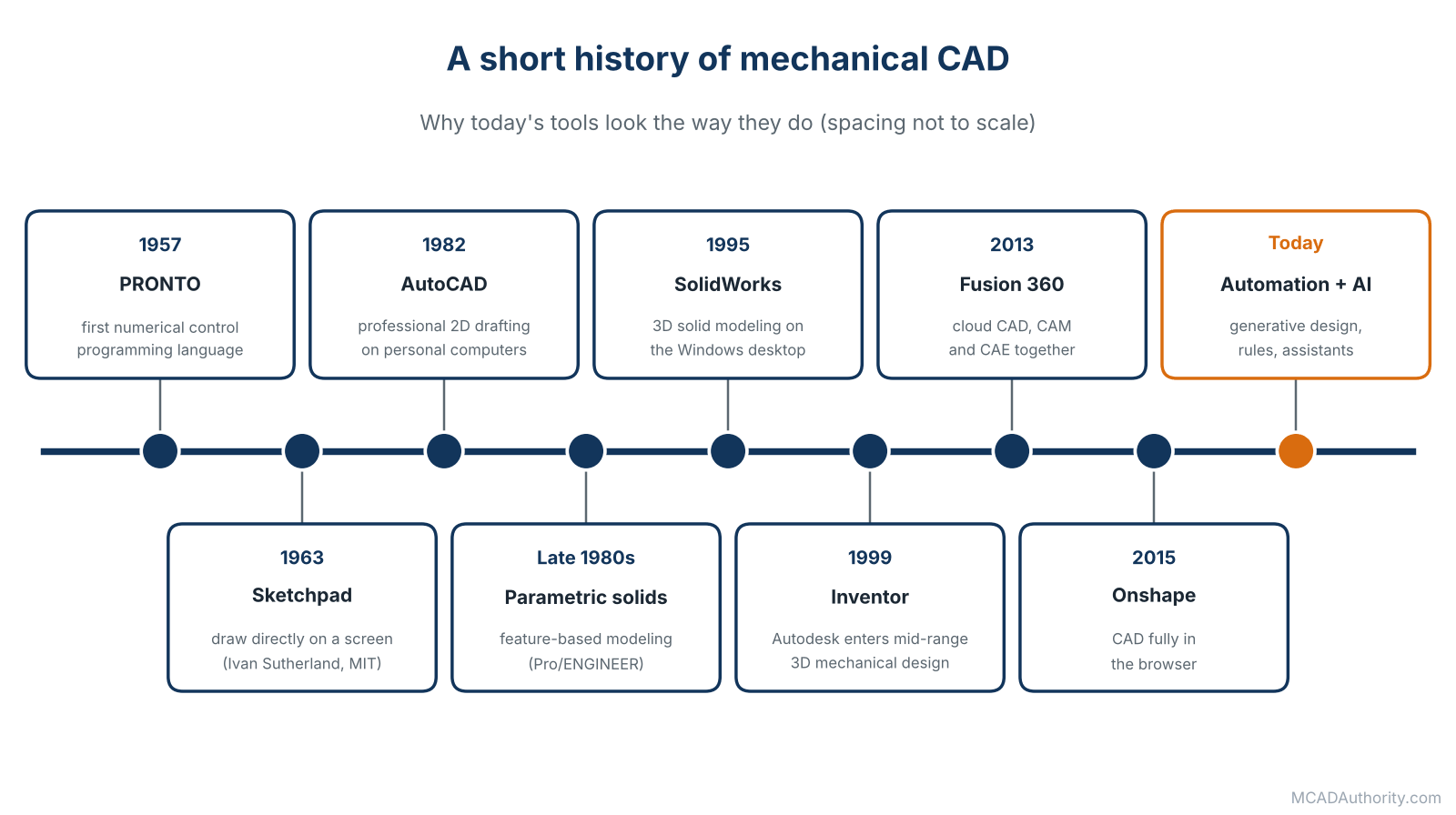
Figure 3. Key milestones in the history of CAD (spacing not to scale).
The lesson I draw from this history is that the concepts are stable while the interfaces change. The designers who thrive are the ones who understand the concepts.
The Main Families of MCAD Software
Not all MCAD tools are built for the same job. Here is how I explain the landscape to new teams.
| Family | What it is | Typical examples |
|---|---|---|
| Mid-range parametric | Full 3D solid modeling with assemblies, drawings and often simulation. The workhorse of small and medium companies. | Autodesk Inventor, SOLIDWORKS, Solid Edge |
| Cloud-native | Runs in a browser or hybrid environment. Strong on collaboration and data management. | Autodesk Fusion, Onshape |
| High-end / enterprise | Built for very large assemblies, complex surfaces and integrated product lifecycle processes. | CATIA, Siemens NX, PTC Creo |
| 2D mechanical drafting | Drawing-based tools with mechanical libraries: standard parts, symbols, bills of materials. | AutoCAD Mechanical, BricsCAD Mechanical |
| Direct and surface modelers | Focus on flexible shape editing or freeform surfaces. | Shapr3D, Rhino, Ansys SpaceClaim |
| Open source | Free, with a more hands-on setup and a smaller ecosystem. | FreeCAD |
If you are choosing a first tool, my advice is simple: pick one that is widely used in the industry you want to work in, learn it deeply, and do not fall for software tribalism. I discuss selection criteria in Best Mechanical CAD Software for Professional Engineers, and students can start on free educational licenses from most vendors.
Who Uses MCAD, and for What?
I have worked with MCAD in settings that look nothing alike, yet the daily work is recognizable everywhere.
- Machinery and automation. Production lines, conveyors, packaging machines, robot cells. Lots of assemblies, lots of standard components, constant change.
- Automotive and transportation. Complex assemblies, tight tolerances, serious data management, strong use of surfaces and simulation.
- Aerospace. Lightweight structures, strict traceability, heavy documentation requirements.
- Medical devices. Small precise parts, regulated documentation and a strong link between design records and compliance.
- Consumer products. Plastic enclosures, industrial design surfaces, injection molding, tight cost targets.
- Tooling and fixtures. Jigs, dies, molds and holding devices, where design speed often matters more than elegance.
- Energy, construction equipment and heavy industry. Large welded frames, structural members, hydraulics and maintenance-driven design.
The job titles vary: mechanical designer, design engineer, drafter, CAD technician, CAD manager, product engineer. I cover the differences in How to Become a Mechanical CAD Designer.
What You Need to Get Started
People overestimate the entry barrier, so let me give you the honest list.
Hardware
You do not need a monster workstation on day one. A reasonably modern computer with a decent processor, plenty of memory (16 GB is a sensible starting point, 32 GB if you plan on large assemblies), an SSD and a dedicated graphics card will carry you a long way. A three-button mouse with a scroll wheel is more important than most beginners think, because you will rotate and pan constantly.
Software
Start with one system. Many vendors offer free student, educator, startup or hobbyist licenses. Cloud tools such as Fusion run on modest machines because part of the work happens remotely, although you will want a stable internet connection.
Knowledge
You need less math than you fear. You need spatial reasoning, which grows quickly with practice, and a basic understanding of how things are made. Knowing the difference between a milled surface and a cast one will make you a better designer than knowing a keyboard shortcut. If you can, spend some time in a workshop or with a machinist. It is the best CAD training money cannot buy.
Habits
The habits that separate a professional from an amateur have little to do with the software: naming files properly, saving versions, working to standards, and checking your own work. I come back to this in Mechanical CAD Standards: A Complete Guide.
Your First 90 Days: A Learning Path That Works
Having taught this for decades, here is the sequence I see produce the best results.
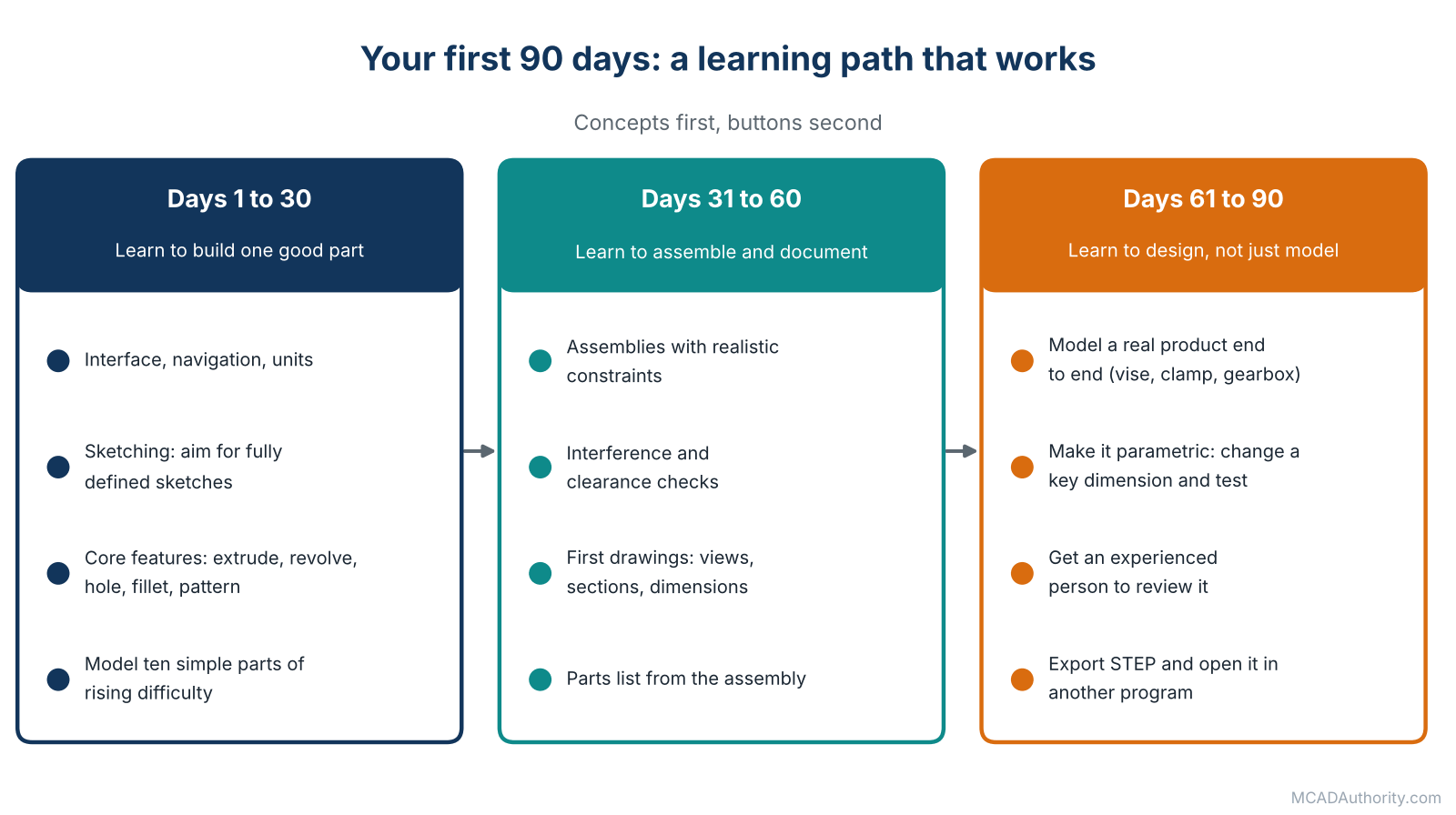
Figure 4. A 90-day path: one good part, then assemblies and drawings, then real design.
Days 1 to 30: Learn to build one good part.
- Learn the interface: navigation, views, selection, units.
- Master sketching, including dimensions and constraints. Aim for fully defined sketches, where nothing is free to float.
- Practice the core features: extrude, revolve, hole, fillet, chamfer, pattern, mirror, shell.
- Model ten simple parts of increasing difficulty. A flange, a bracket, a pulley, a housing.
Days 31 to 60: Learn to assemble and document.
- Build assemblies using constraints that reflect real contact and motion.
- Check interference and clearance.
- Create your first drawings, with standard views, sections, dimensions and a title block.
- Generate a parts list from an assembly.
Days 61 to 90: Learn to design, not just model.
- Take a real object, such as a vise, a small gearbox or a clamp, and model it completely, from parts to drawings.
- Make it parametric: change a key dimension and see whether the model survives.
- Ask someone experienced to review it.
- Export a STEP file and open it in another program, to see how data exchange behaves.
If you want structured exercises for this stage, Mechanical CAD Practice Exercises for Beginners gives you a progression you can follow.
The Mistakes Every Beginner Makes (I Made Them Too)
- Modeling before thinking. Opening the software and clicking before you know what the part must do. A five-minute sketch on paper saves an hour of rebuilding.
- Under-defined sketches. Leaving lines free to move because “it looks right”. It will look wrong the day someone edits it.
- Dimensioning for appearance, not intent. Every dimension should answer a question about function or manufacturing. This is the heart of Understanding Design Intent in 3D Mechanical Modeling.
- Ignoring how it is made. A beautiful part with a sharp internal corner that no milling cutter can produce is not a good part.
- Giant, tangled feature trees. Fifty features where fifteen would do. Future you, or a colleague, will pay for this.
- No file discipline. Files called
final,final2andfinal_REAL. I have seen entire projects lost to this. - Trusting the software blindly. The program will happily let you design a part that cannot be manufactured, assembled or sold. Responsibility remains yours.
For a fuller list, see Common Mistakes Beginners Make in Mechanical CAD.
How MCAD Fits Into the Bigger Picture
MCAD does not live alone. It sits in the middle of a chain of activities, and understanding the neighbors will make you far more valuable.
- Upstream, requirements, concepts and industrial design feed the model.
- Alongside, simulation (CAE) tests it. You can start with Computer-Aided Engineering (CAE): A Complete Beginner’s Guide.
- Downstream, manufacturing (CAM, CNC, molding, 3D printing, fabrication) turns the model into physical parts.
- Around it, data management (PDM and PLM) controls versions, approvals and changes, as explained in Product Data Management (PDM): A Complete Guide.
The full journey, from the first idea to the finished part, is the subject of The Complete Mechanical CAD Workflow: From Concept to Manufacturing, and I would encourage you to read it right after this guide.
Final Thoughts
After more than thirty years, I still enjoy the moment when a shape I have only imagined appears on screen, turns on its axis, and then, weeks later, arrives from the workshop as a real object that fits on the first try. MCAD is a craft, and like any craft it rewards patience, curiosity and respect for the fundamentals.
Start with one tool. Learn the concepts, not the buttons. Build real things, even small ones. Keep your files tidy. Ask for reviews. And remember that the software will change every year, but a designer who understands intent, manufacturing and documentation will always be employable.
Where to go next: read Mechanical CAD vs. General-Purpose CAD: Key Differences Explained to place MCAD in the wider CAD family, then 2D CAD vs. 3D CAD in Mechanical Engineering to understand why modern design is built on solid models while 2D still matters.