

I keep a notebook. It is not the one with my to-do lists; it is a worn, coffee-stained book in which, for more than thirty years, I have written down every mistake that cost somebody time or money in a design office, mine included. It has hundreds of entries, and here is the strange thing: after the first fifty or so, the entries start to repeat. The names change, the software changes, the industries change, but the same mistakes keep coming back, generation after generation of beginners.
That is good news for you. It means you do not have to discover these mistakes the expensive way. In this guide I will go through the twenty-five I see most often, grouped by the stage of work where they appear, with the reason each one happens, what it costs and how to avoid it. I made nearly all of them myself, so there is no judgment here, only experience.
If you are just starting out, read What Is Mechanical CAD (MCAD)? A Complete Beginner’s Guide and How to Become a Mechanical CAD Designer alongside this one.
The Short Answer
Almost every beginner mistake in CAD comes from one of five root causes:
- Not thinking before modeling. The mouse moves before the plan exists.
- Modeling what it looks like, not how it works. Appearance is captured, intent is not.
- Forgetting the reader. The machinist, the buyer, the colleague who will edit your file are invisible during modeling.
- Trusting the screen. Software accepts almost anything. That does not make it right.
- Working alone. No review, no feedback, no learning from other people’s mistakes.
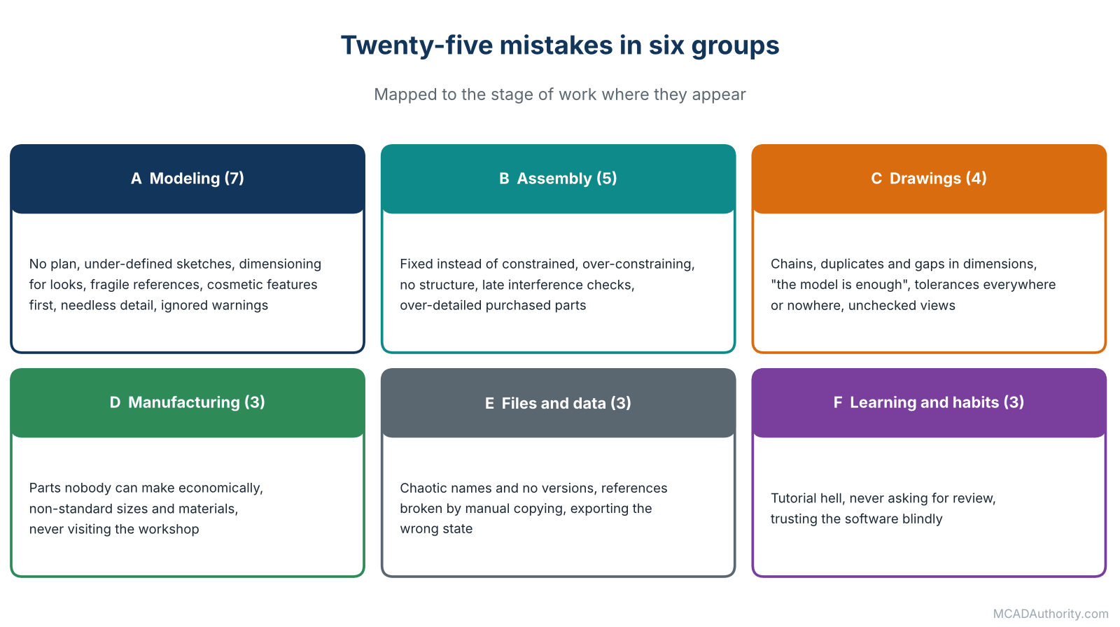
Figure 1. The twenty-five mistakes, grouped by stage of work.
Keep these five in mind as you read, and notice how each mistake below maps to one of them.
Group A: Modeling Mistakes
1. Starting to model without a plan
What happens. You open the software and start sketching a profile in the first plane that comes to hand. Twenty features later, you realize the part should have been built differently, and you cannot easily change it.
What it costs. Hours of rework, and a feature tree that is a monument to indecision.
The fix. Spend five minutes on paper first. Ask: What is the part for? What are its key dimensions? What is the first, biggest feature? Which dimensions are likely to change? Which features are cosmetic? Then model. This habit alone will improve your work more than any shortcut.
2. Leaving sketches under-defined
What happens. The sketch “looks right”, so you move on, leaving some lines free to move. Everything works until someone edits a dimension and a line leaps to a new position.
What it costs. Unpredictable behavior, broken features, mistrust in your models.
The fix. Make every sketch fully defined: all geometry fixed by dimensions and constraints, nothing floating. Anchor the sketch to the origin or to meaningful reference geometry. For troubleshooting, see Resolving Overdefined and Underdefined Sketches.
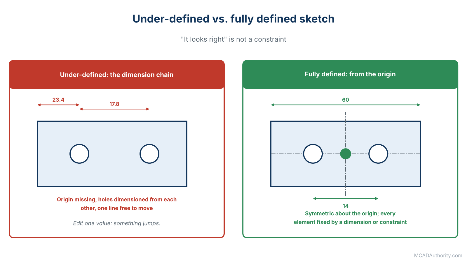
Figure 2. The same plate, sketched two ways.
3. Dimensioning for appearance instead of intent
What happens. You dimension whatever is easiest to read: a hole 23.4 mm from this edge, 17.8 mm from that one, because that is how the geometry happened to land.
What it costs. The model works today and fights you tomorrow. Worse, the drawing inherits odd dimensions that mean nothing to the machinist.
The fix. Dimension for function and manufacturing. Ask of each dimension: “Does it relate to a requirement? Would someone want to change it directly? Is it where the workshop will measure from?” This is the heart of Understanding Design Intent in 3D Mechanical Modeling.
4. Building on fragile references
What happens. You attach a sketch to the face created by a small fillet, or dimension to the edge of a chamfer. Later the fillet changes, and everything depending on it fails.
What it costs. The classic red-flagged feature tree and an afternoon of repair. See How to Fix Failed Features in Parametric CAD Models.
The fix. Attach sketches and features to stable geometry: origin planes, primary faces, named reference planes. Avoid referencing things you know are likely to change. For a complete strategy see How to Build a Clean and Reliable CAD Feature Tree and How to Prevent Feature Failures in Parametric CAD Models.
5. Putting cosmetic features too early
What happens. You add fillets and chamfers as you go, early in the history. Then you need to change a basic feature, and the fillets block you.
What it costs. Failed rebuilds and endless fiddling.
The fix. Build in the order of importance: primary shape first, functional features next, finishing features last. Your feature tree should read like a sensible recipe.
6. Modeling details nobody needs
What happens. You model every thread of every screw, the engraved logo, tiny fillets that will be produced by a cutter anyway.
What it costs. Heavy files, slow rebuilds, and no extra information for anyone.
The fix. Model to the level of detail the purpose requires. Use cosmetic threads, standard library components and simplified representations. A thread note on a drawing communicates more than a spiral on the model.
7. Ignoring warnings and errors
What happens. The software shows a warning or a small yellow triangle. You click “continue” because the model looks fine.
What it costs. Small problems accumulate until a rebuild fails or a drawing goes wrong, and by then nobody remembers which warning mattered.
The fix. Treat warnings as messages from a colleague. Read them. Understand them. Fix the cause. Mechanical CAD Troubleshooting: A Complete Guide helps you decode the common ones.
Group B: Assembly Mistakes
8. Fixing components in space instead of constraining them
What happens. To save time you “ground” or fix parts where they are placed, instead of mating them to each other.
What it costs. The assembly looks right but does not behave. You cannot test motion, and moving one part leaves everything else behind.
The fix. Ground one component, usually the base, and constrain the rest to real relationships: a face against a face, a pin in a hole. See Understanding Assembly Constraints, Mates, and Joints.
9. Over-constraining
What happens. You add every constraint you can think of, “just to be sure”.
What it costs. Conflicts, warnings, and an assembly that refuses to move or rebuild.
The fix. Constrain only what the real world constrains. If a shaft is free to rotate, leave it free to rotate. Understand the degrees of freedom you are removing. See Degrees of Freedom in Mechanical Assemblies Explained.
10. No structure in the assembly
What happens. All 300 parts live in a single flat assembly, with no subassemblies.
What it costs. Slow performance, a useless BOM and a nightmare for anyone else working on it.
The fix. Mirror the structure in which the product is built and serviced: drive unit, frame, guarding, standard hardware. See Understanding Parts, Assemblies, Drawings, and BOMs in MCAD and Assembly Modeling in Mechanical CAD: A Complete Guide.
11. Checking interference at the end
What happens. You wait until the last day to look for collisions.
What it costs. A late discovery that the motor cable hits the moving carriage, or that no tool can reach a bolt.
The fix. Assemble early and often. Run interference and clearance checks at every milestone. See Interference Detection and Clearance Analysis in MCAD.
12. Over-detailed purchased components
What happens. You download a supplier’s model of a motor with every internal part, and drop it into your assembly.
What it costs. An assembly that takes minutes to open.
The fix. Use simplified models or simplified representations of purchased items. You need their envelope, mounting points and connections, not their innards. See How to Create and Manage Large CAD Assemblies.
Group C: Drawing Mistakes
13. Dimensioning errors: chains, duplicates and gaps
What happens. Dimensions form long chains that accumulate tolerance, appear twice with slightly different values or, worse, are missing entirely.
What it costs. Parts that do not fit, queries from the shop, scrap.
The fix. Dimension from functional datums, give each feature its size and location once, and verify that nothing a machinist needs must be calculated. See Engineering Dimensioning: Rules and Best Practices.
14. “They can get it from the model”
What happens. You send the 3D file and skip the notes, material, finish or tolerances on the drawing.
What it costs. The workshop guesses. Guesses are expensive.
The fix. Unless your company has a formal model-based practice, the drawing is the contract. Include material, finish, heat treatment, general tolerances and critical notes. See Mechanical Engineering Drawings: A Complete Guide and Model-Based Definition (MBD) and 3D Product Manufacturing Information (PMI).
15. Tolerances everywhere, or nowhere
What happens. Beginners either tolerate every dimension tightly “to be safe”, or leave everything to a default.
What it costs. Tight tolerances raise cost dramatically; missing tolerances produce parts that do not fit.
The fix. Tighten only where function demands it, and let a general tolerance block cover the rest. Learn fits and basic GD&T. See Fits and Tolerances: Clearance, Transition, and Interference Fits, Manufacturing Tolerances and Their Impact on Product Cost and Geometric Dimensioning and Tolerancing (GD&T): A Complete Guide.
16. Not checking the drawing itself
What happens. You trust the automatically generated views and skip the review: wrong scale, wrong projection symbol, a section that cuts the wrong place, a dimension that fell off.
What it costs. Credibility, and sometimes a batch of wrong parts.
The fix. Review every drawing as if you were the machinist. Print or zoom, check each dimension against the model, confirm title block data. Then ask a colleague to review it.
Group D: Manufacturing Mistakes
17. Designing parts nobody can make economically
What happens. A sharp internal corner no milling cutter can produce. A wall too thin to mold. A bend too close to a hole. A pocket too deep and narrow.
What it costs. Phone calls, redesign, delays, cost.
The fix. Learn the basic rules of the processes you design for. Ask, for every feature: “How will this be made?” See Design for Manufacturing (DFM) and Design for Assembly (DFA): A Complete Guide.
18. Ignoring standard sizes and materials
What happens. You specify a 17.3 mm hole, a 5.7 mm thick plate and a custom screw.
What it costs. Special tools, special orders, long lead times.
The fix. Use standard sizes, standard stock thicknesses and standard fasteners wherever you can. See Materials Selection Guide for Mechanical Design and Managing Standard Parts and CAD Component Libraries.
19. Never visiting the workshop
What happens. The only people who see your drawings are other designers.
What it costs. You do not learn what annoys the machinist, the welder or the assembler, so you repeat the same errors.
The fix. Walk to the workshop. Watch parts being made. Ask what they would change on your drawings. I have learned more from ten minutes beside a milling machine than from many manuals.
Group E: File and Data Mistakes
20. Chaotic file names and no versioning
What happens. Files called bracket_final, bracket_final2, bracket_final_REAL, bracket new.
What it costs. Nobody knows which one is current. Someone eventually manufactures from the wrong one.
The fix. Adopt a naming and numbering convention from day one, and use proper revision control. See Mechanical CAD File Naming and Part Numbering Standards and Product Data Management (PDM): A Complete Guide.
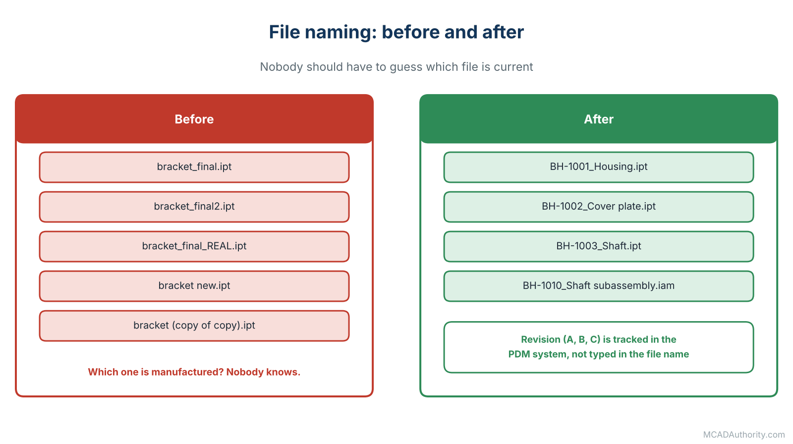
Figure 3. File names before and after a naming convention.
21. Breaking references by moving or copying files by hand
What happens. You copy a project folder in your file explorer, rename a part there and open the assembly: “missing file”.
What it costs. Broken assemblies and drawings, lost hours.
The fix. Rename, move and copy files from within the CAD or PDM system, so references update. Keep a clean project structure. See How to Repair Broken Assembly References.
22. Exporting the wrong thing
What happens. You send a STEP file exported from an out-of-date assembly state, with suppressed parts or the wrong configuration, or in the wrong units.
What it costs. A supplier quotes or machines the wrong thing.
The fix. Check what you are exporting, then open the exported file in a different program to verify. See Mechanical CAD File Formats: A Complete Guide and Repairing Imported CAD Models: Common Problems and Solutions.
Group F: Learning and Professional Mistakes
23. Tutorial hell
What happens. You follow video after video, copying clicks, and never design anything of your own.
What it costs. You can reproduce someone else’s model but cannot start from a blank screen.
The fix. After each tutorial, close it and model something similar from a drawing, then something original. Learn concepts, not click sequences. See Mechanical CAD Practice Exercises for Beginners.
24. Never asking for review
What happens. You work alone and release when you feel finished.
What it costs. Mistakes that anyone else would have spotted in thirty seconds go through.
The fix. Ask a colleague, a mentor or a community to review your work, and say clearly: “Please try to find something wrong.” Build the checklist into your routine. See Mechanical CAD Model Review and Quality Assurance Checklist.
25. Trusting the software blindly
What happens. The model rebuilt without errors, the simulation produced colors, the interference check says “none”. So it must be right.
What it costs. Overconfidence. The software verifies geometry, not engineering judgment. Simulation results depend entirely on the assumptions fed in.
The fix. Sanity-check everything: estimate by hand, compare with a similar known design, question surprising results. Remember: a program will happily let you design a part that cannot be made, assembled or sold.
The Pre-Release Self-Review
Before you let any design leave your hands, run through this short list. It takes ten minutes and catches most of the mistakes above.
- Are all sketches fully defined, with no warnings in the model?
- Do key dimensions change the model without breaking it? (Change one, see what happens.)
- Is the feature tree short, ordered and named sensibly?
- Does the assembly have structure, correct constraints and no unexpected interference?
- Does every part have material, part number and description?
- Does each drawing contain views, dimensions, tolerances, notes, title block and revision?
- Did I check every dimension a machinist needs against the model?
- Could every feature actually be made, with standard tools and sizes?
- Are files named correctly and stored in the managed location?
- Has someone else reviewed it?
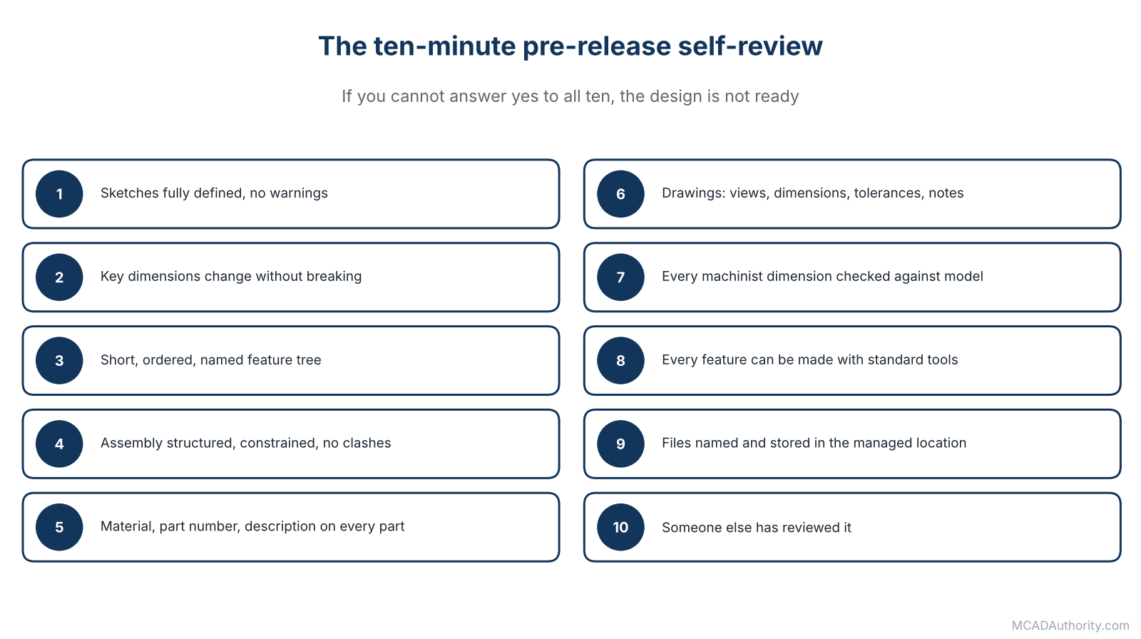
Figure 4. The ten-minute self-review that catches most beginner mistakes.
If you cannot answer “yes” to all ten, the design is not ready.
How to Learn From Your Own Mistakes Faster
- Keep a mistake log. Date, what happened, what it cost, how you fixed it, how you will avoid it. Review it monthly.
- Do a short “post-mortem” after each project. What worked? What did we waste time on?
- Create personal templates and checklists. Turn each lesson into a reusable tool.
- Pair with someone more experienced for an hour a month, and let them review a real file.
- Share your mistakes. A team that talks openly about errors makes far fewer.
Final Thoughts
Mistakes are not the enemy. In design they are the raw material of experience, provided you notice them early, learn from them and do not hide them. The difference between a beginner and a professional is not that the professional makes no errors; it is that the professional has systems that catch them before they leave the building: a plan before modeling, standards, review, a visit to the workshop, a checklist.
Start by choosing three mistakes from this list that you recognize in your own work. Fix those first. Next month, choose three more. Within a year you will be working very differently, and the notebook I started a long time ago will have fewer new entries from you.
Where to go next: put these ideas into practice with Mechanical CAD Practice Exercises for Beginners, and read Understanding Design Intent in 3D Mechanical Modeling to understand the single biggest source of good models.