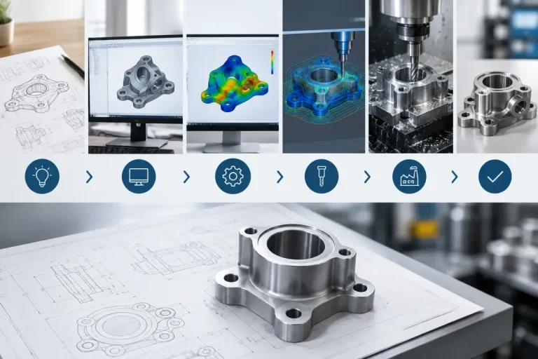

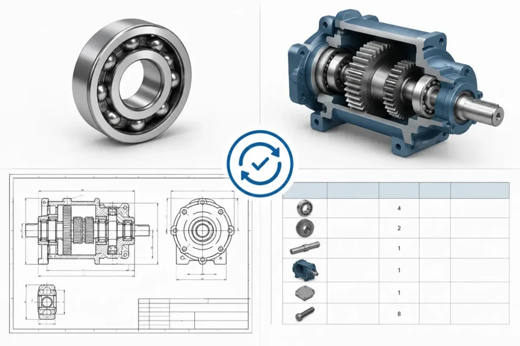

Early in my career, I watched a purchasing clerk order forty ball bearings for a machine that needed four. The drawing was correct. The 3D assembly was correct. The parts were correct. But the bill of materials had been typed by hand into a spreadsheet, and somewhere between the assembly and the spreadsheet a zero had appeared. Forty bearings arrived on a pallet. The supplier would not take them back. The company did not need them for another six years.
That small disaster taught me the lesson I now teach on the first day of every MCAD course: a mechanical design is not one thing, it is four things that must agree with each other. The part, the assembly, the drawing and the BOM are like the four legs of a table. If one of them is out of line, the table wobbles. If two are out of line, someone will eventually get hurt, usually financially.
In this guide I will explain what each of the four really is, what information lives where, how they relate, how to structure them well and how to keep them consistent. The principles apply to every serious MCAD system, including Autodesk Inventor, Fusion, SOLIDWORKS, Creo and NX. If you are new to the field, you may want to read What Is Mechanical CAD (MCAD)? A Complete Beginner’s Guide first, and keep Essential Mechanical CAD Terminology Every Designer Should Know nearby.
The Short Answer
| Deliverable | What it answers | Who relies on it |
|---|---|---|
| Part | What is this single component, exactly? | Designers, analysts, manufacturers |
| Assembly | How do the components fit and work together? | Designers, assemblers, service teams |
| Drawing | How must it be made, checked and accepted? | Machinists, suppliers, quality inspectors |
| BOM | What must be bought or made, and how many? | Purchasing, production planning, finance |
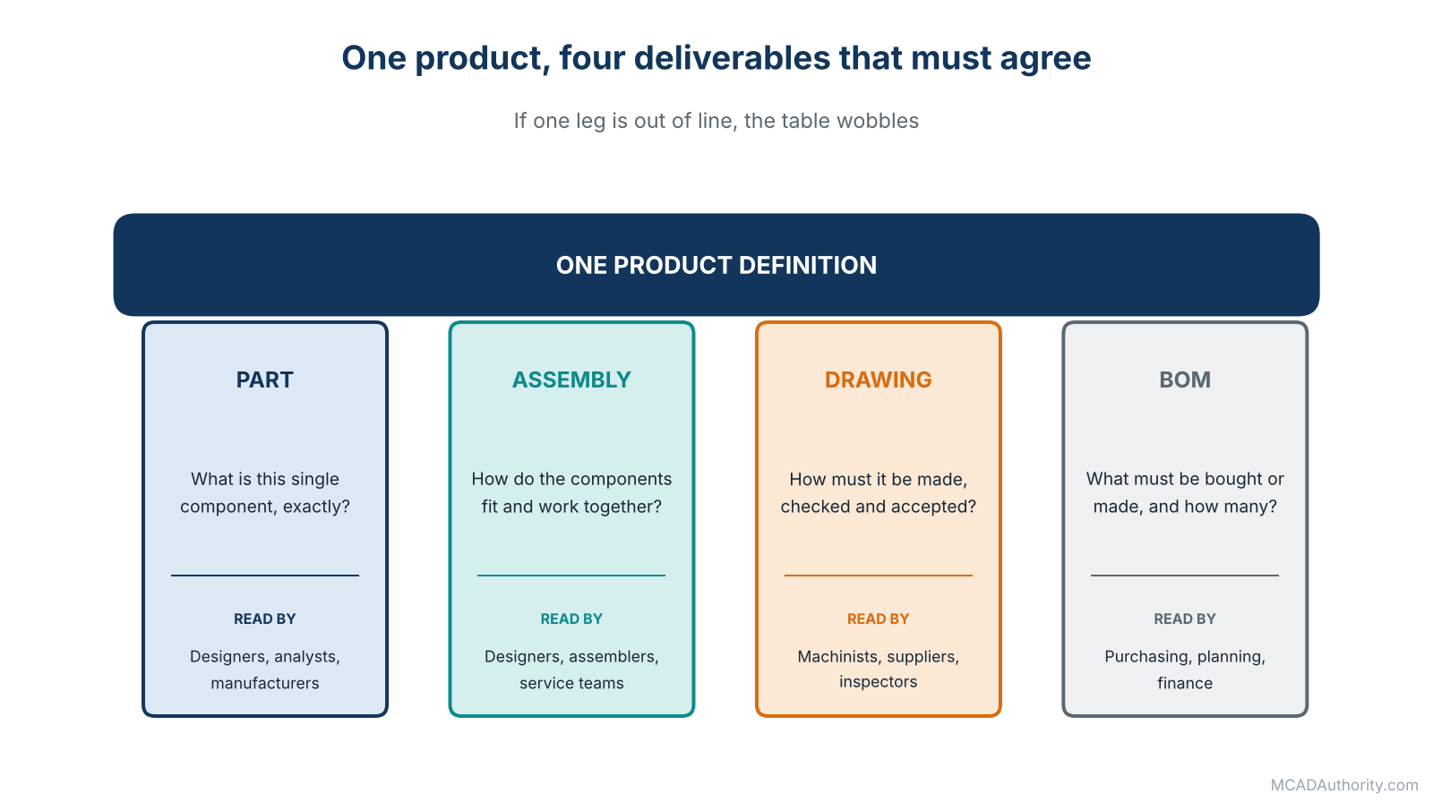
Figure 1. Four deliverables, one product definition.
And the way they connect:
PART  ──(placed in)──▶  ASSEMBLY  ──(generates)──▶  BOM
  │                        │                         │
  └──(documented by)──▶  DRAWING  ◀──(balloons / parts list)──┘
The parts feed the assembly. The assembly feeds the BOM. The drawings document the parts and the assembly, and they display the BOM. All four are views of one underlying product definition, and the art of professional MCAD work is keeping that definition consistent.
Part One: The Part
What a part is
A part is a single component, usually one manufactured or purchased item, made from one material. A bracket, a shaft, a cover, a spacer, a bearing. In the model, the part file contains:
- Geometry: the 3D shape, built from sketches and features.
- Material: steel, aluminum, plastic, rubber. This determines mass, appearance and often cost.
- Properties (metadata): part number, description, supplier, finish, weight, designer and so on.
- History: the recorded sequence of features, when the model is parametric.
- Parameters: named dimensions and formulas that drive the shape.
How to decide: is it one part or several?
This question arises constantly, and I use a simple set of tests. Something should be its own part if:
- It is made separately. It is cut, machined or molded as its own piece.
- It is made from a different material. A steel pin in an aluminum housing is two parts.
- It can be purchased, stocked or replaced on its own. If a technician would order it by itself, it is a part.
- It moves relative to something else. A hinge pin turns inside a hinge.
- It is joined by a removable connection. Screwed, clipped or pressed, and later separable.
Conversely, something belongs inside one part if it is made in one operation from one piece of material, such as a boss on a casting, a flange on a shaft or a rib on a molded cover. In that case, it is a feature, not a part.
Kinds of parts you will meet
- Custom manufactured parts: designed by you, made to your drawing.
- Standard (catalog) parts: screws, nuts, washers, pins, bearings, circlips. Taken from libraries. See Managing Standard Parts and CAD Component Libraries.
- Purchased components: motors, cylinders, sensors, gearboxes. Often modeled as simplified shapes, with the supplier’s part number.
- Sheet metal parts: bent models with a flat pattern. See Sheet Metal Design in 3D CAD: A Complete Guide.
- Weldment components: profiles, plates and cut lengths used in frames. See Weldment Design and Modeling in Mechanical CAD.
- Multi-body parts: one file containing several solids, used for design workflows and then split into individual parts. See Multi-Body Modeling: Techniques and Best Practices.
- Derived or reference parts: parts that take their geometry from another part, such as a mold cavity from a product.
- Virtual or phantom components: items with no geometry that exist only to appear in the BOM, such as glue, paint or a cable kit.
Habits that make good parts
- One part, one purpose. Do not turn a part file into a dumping ground.
- Assign the material every time. A part without material has no mass.
- Fill in the properties consistently: number, description, finish. See Mechanical CAD File Naming and Part Numbering Standards.
- Name the file to match the part number, or follow your company’s rule.
- Model purchased parts simply. A motor does not need every screw thread inside.
- Keep the feature tree readable. See How to Build a Clean and Reliable CAD Feature Tree.
- Build with intent. See Understanding Design Intent in 3D Mechanical Modeling.
For the modeling techniques themselves, Parametric 3D Modeling: A Complete Practical Guide is the place to go.
Part Two: The Assembly
What an assembly is
An assembly combines parts and subassemblies into a working whole. It records:
- Which components are included and how many of each.
- Where they are positioned, through constraints, mates or joints.
- How they move, if the assembly is a mechanism.
- How the product is organized, through its hierarchy.
Assembly structure: the hidden skeleton of your product
Assemblies are organized in levels. A top-level assembly contains subassemblies, which contain parts, and sometimes more subassemblies. For example:
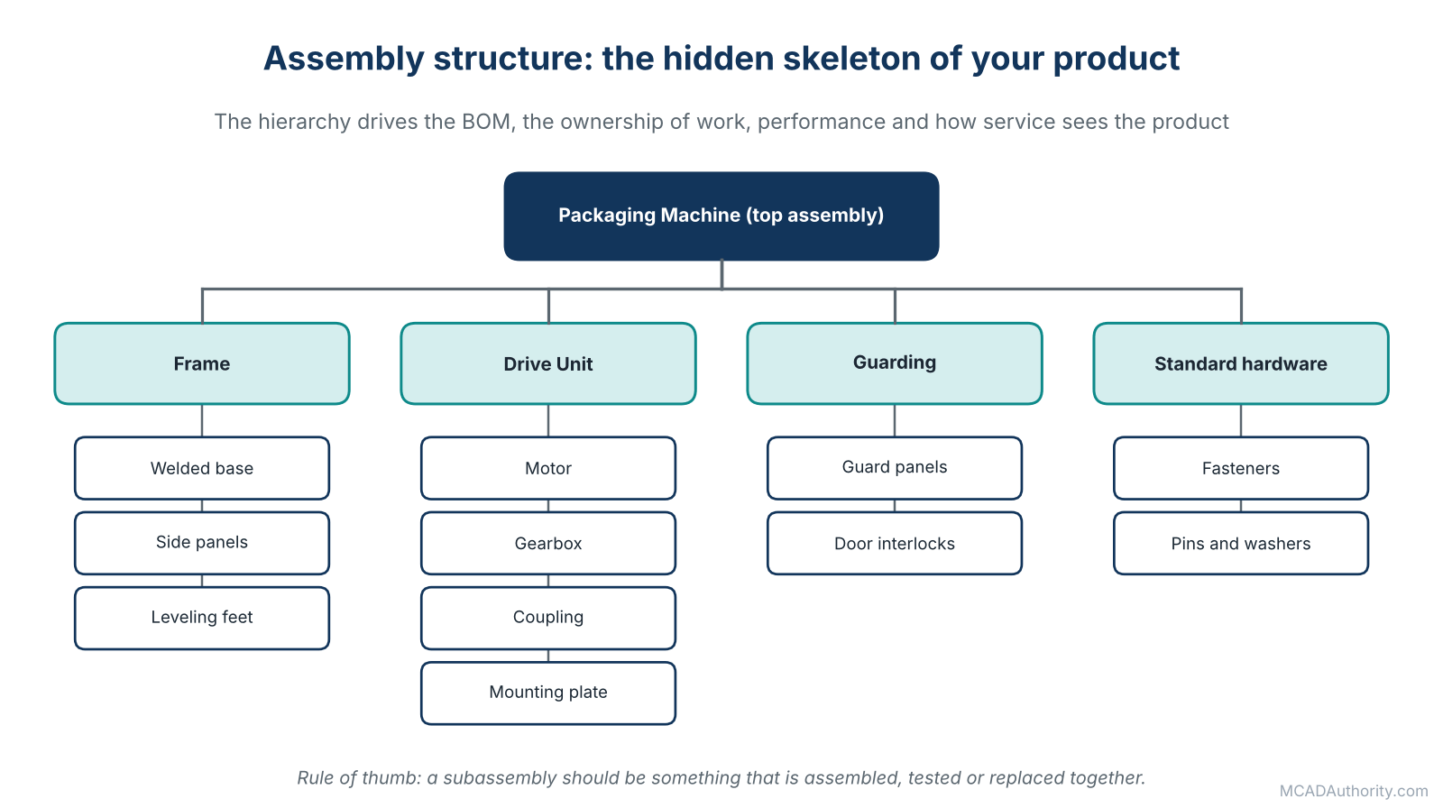
Figure 2. A product’s assembly hierarchy defines its BOM structure, work ownership and performance.
This hierarchy is more than a convenience. It determines the BOM structure, the ownership of work between designers, the performance of the model, and the way production and service people will see the product.
Rules of thumb for good structure
From many years of fixing other people’s assemblies, these are my principles.
- Mirror how the product is built and serviced. A subassembly should correspond to something that is assembled together, tested together or replaced together.
- Keep modules independent. A drive unit should be assemblable without the guarding.
- Avoid a flat structure. Five hundred parts in one assembly is slow, confusing and hard to manage.
- Avoid excessive depth. Too many nested levels make navigation and BOMs painful. I rarely like to see more than five or six levels without a clear reason.
- Place standard hardware sensibly. Some companies list fasteners in the subassembly where they are used; others group them. Choose a rule and follow it.
- Use consistent naming. A reader should know what a subassembly contains from its name.
- Plan the structure early. It is much harder to reorganize an assembly after hundreds of parts have been added.
The details of structure, constraints and top-down methods are covered in Assembly Modeling in Mechanical CAD: A Complete Guide and Best Practices for Assembly Structure and Component Organization.
Constraints: how components stay where they belong
Components are positioned using constraints (called mates in some systems and joints in others). A well-constrained assembly:
- Positions each part by real functional relationships: face against face, axis aligned with axis.
- Leaves only the intended freedom of movement.
- Avoids fixing parts arbitrarily in space.
- Rebuilds without errors after edits.
See Understanding Assembly Constraints, Mates, and Joints and Degrees of Freedom in Mechanical Assemblies Explained.
Assembly-level features and processes
Some operations happen in the assembly environment, not in the parts, because they represent processes that occur after assembly. A typical case is drilling a hole through two parts that are welded together first. The model should reflect how the product is actually made.
Checks you do in assemblies
- Interference detection: finding collisions between components.
- Clearance analysis: ensuring gaps are large enough.
- Motion testing: driving mechanisms through their range.
- Mass properties: total weight and center of gravity.
- Accessibility: can tools and hands reach the fasteners?
These checks are explained in Interference Detection and Clearance Analysis in MCAD.
Configurations and variants
Many products exist in several sizes or versions. Rather than duplicating assemblies, professional systems provide configurations, family tables or iAssemblies (Autodesk Inventor’s term). They keep variants within one structure, so that a change to the common design reaches all versions. This is explained in Assembly Configurations and Flexible Subassemblies Explained.
Part Three: The Drawing
What a drawing is, and why it still matters
A drawing is the formal 2D document describing a part or assembly. It is often called the “contract” between the designer and the manufacturer, because it states what is to be made and what is acceptable.
A single drawing typically carries:
- Views: front, top, side, sections, details, isometric.
- Dimensions: sizes and positions.
- Tolerances: permitted variation, including geometric tolerances (GD&T).
- Material and finish: specified by note or title block.
- Notes: heat treatment, deburring rules, inspection requirements.
- Title block: part number, description, scale, units, projection symbol, author, date, revision.
- Revision history: a record of approved changes.
Types of drawings
- Part drawing (detail drawing): one part, fully dimensioned for manufacturing.
- Assembly drawing: shows how parts fit together, with balloons and a parts list.
- Exploded assembly drawing: shows components separated for assembly or service.
- Weldment or fabrication drawing: includes weld symbols, cut lists and sequences.
- Installation drawing: shows how the product connects to its surroundings.
- Layout drawing: a general arrangement or reference for design.
- Sheet metal drawing: with flat pattern, bend information and finishes.
Drawings are generated, not drawn
In an MCAD system, a drawing is associative: the views come from the 3D model. Change the model and the views update. That means:
- Views can never disagree with each other.
- Sections and details come from actual geometry.
- Dimensions can be retrieved from the model, ensuring they match.
- Parts lists are generated from the assembly.
The craft lies in annotating the views well: choosing what to dimension, how to tolerance, where to place notes and how to make the drawing readable by a person who has never seen the model. See Mechanical Engineering Drawings: A Complete Guide, How to Create Manufacturing Drawings from 3D CAD Models and Engineering Dimensioning: Rules and Best Practices.
Standards behind drawings
Drawings follow national or international standards, such as the ASME Y14 series in North America and the ISO drawing and GPS standards elsewhere. They define line types, view arrangement, dimensioning rules and symbols. Your company should choose one and apply it consistently. See Engineering Drawing Standards: ASME, ISO, ANSI, and DIN and Geometric Dimensioning and Tolerancing (GD&T): A Complete Guide.
What about the model-based alternative?
Some industries are moving toward annotating the 3D model itself with dimensions and tolerances, using Model-Based Definition. It is a real and growing practice, introduced in Model-Based Definition (MBD) and 3D Product Manufacturing Information (PMI). But in most workshops today, the drawing remains the document that is printed, signed and followed. Learn it well.
Which one wins if the model and drawing disagree?
This is a question every company must answer in writing. In most traditional environments, the released drawing governs, because it is the contractual document. In a model-based environment, the model may govern. What matters is that the rule is explicit and that people check for disagreement before release.
Part Four: The BOM
What a BOM is
A bill of materials is a structured list of everything that makes up a product: the parts, subassemblies, standard components and sometimes consumables, with quantities and key properties. It is the bridge between the designer’s digital world and the company’s commercial world.
Typical columns:
- Item number: the position in the list, matching balloons on drawings.
- Quantity.
- Part number.
- Description.
- Material.
- Mass or other properties.
- Supplier or manufacturer reference, for purchased parts.
- Notes, such as finish or special treatment.
Types of BOM views
Most MCAD systems can present the same data in several ways. In Autodesk Inventor, for example, the BOM editor offers a structured view and a parts-only view. Similar choices exist elsewhere.
| BOM view | What it shows | Typical use |
|---|---|---|
| Structured (indented, multi-level) | The full hierarchy: assemblies, subassemblies and parts, with quantities at each level | Production planning, assembly sequences, service |
| Parts-only (flat, consolidated) | Every unique part with the total quantity across the whole product | Purchasing, cost estimation, stock control |
| First-level | Only the immediate children of one assembly | Assembly drawings, work instructions |
Choosing the right view for the reader is half the work of making a useful BOM.
Where the BOM comes from
In a well-run system, the BOM is generated from the assembly structure and part properties, not typed. The software counts instances, reads the properties and compiles the table. That is why assembly structure and part metadata matter so much: they become the BOM.
Beyond the model: what a BOM must also include
Real products include things that rarely appear as full 3D models:
- Consumables: adhesive, grease, thread locker, paint.
- Bulk items: cables, hoses, tubing, sold by length.
- Kits: bundles of items purchased together.
- Labels, packaging and documentation.
- Items that are modified after purchase, such as a purchased shaft that is machined further.
These are usually handled with virtual components, custom BOM entries or an ERP system. If you forget them in the BOM, production will remember them for you, loudly.
Engineering BOM vs. manufacturing BOM
The designer’s BOM (organized by function and design structure) is often not the same as the BOM production needs (organized by the order of assembly, with intermediate stages and kits). Many companies maintain both and connect them. See Engineering BOM vs. Manufacturing BOM: Key Differences and Bill of Materials (BOM) Management in Mechanical CAD.
A Worked Example: A Small Bearing Housing
To make this concrete, consider a simple shaft support assembly. The table below is a parts-only BOM, as purchasing would read it.
| Item | Qty | Part number | Description | Material / spec |
|---|---|---|---|---|
| 1 | 1 | BH-1001 | Housing | Aluminum alloy, machined |
| 2 | 1 | BH-1002 | Cover plate | Aluminum alloy, machined |
| 3 | 1 | BH-1003 | Shaft | Steel, turned and ground |
| 4 | 2 | BRG-6205 | Deep groove ball bearing 6205 | Purchased |
| 5 | 1 | SL-2552 | Radial shaft seal 25 x 52 | Purchased, rubber |
| 6 | 4 | ISO-4762-M6x16 | Socket head cap screw M6 x 16 | Steel, zinc plated, purchased |
| 7 | 2 | ISO-8734-6×14 | Dowel pin 6 x 14 | Steel, purchased |
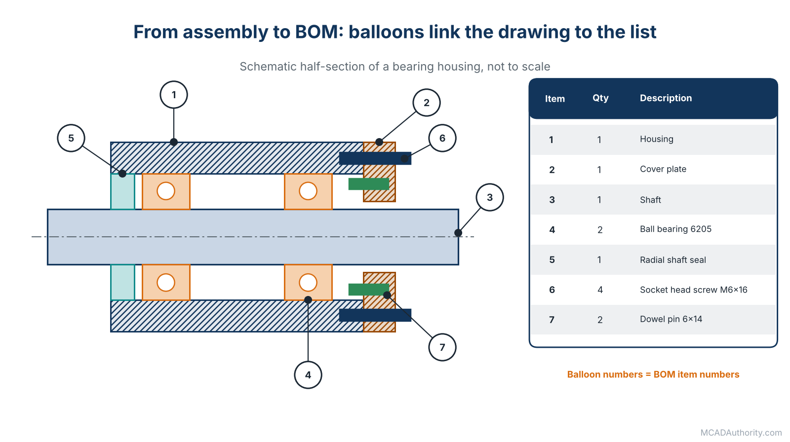
Figure 3. Balloons on the assembly drawing match the item numbers in the BOM.
And here is how the same product might look in a structured BOM:
Bearing Housing Assembly (BH-1000)
├── Housing (BH-1001) x1
├── Cover plate (BH-1002) x1
├── Shaft subassembly (BH-1010) x1
│   ├── Shaft (BH-1003) x1
│   └── Deep groove ball bearing 6205 (BRG-6205) x2
├── Radial shaft seal (SL-2552) x1
├── Socket head cap screw M6 x 16 (ISO-4762-M6x16) x4
└── Dowel pin 6 x 14 (ISO-8734-6x14) x2
Notice how the same information supports two readers. The purchaser sees one line for bearings with total quantity. The assembler sees the shaft with its bearings as one step. The data is the same; the view is different.
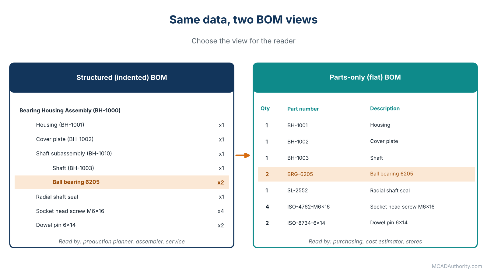
Figure 4. The same data, two BOM views for two kinds of reader.
Now imagine the drawings. Each manufactured part has a drawing: the housing, the cover and the shaft. The assembly drawing shows the whole thing with balloons numbered 1 to 7, matching the BOM. A machinist reads the housing drawing, a buyer reads the BOM, an assembler reads the assembly drawing and a technician reads an exploded view. Four people, four documents, one product, and all of them must agree.
Where Does Each Piece of Information Live?
A frequent source of errors is storing information in the wrong place, or in several places. This table shows my recommended home for each type of data.
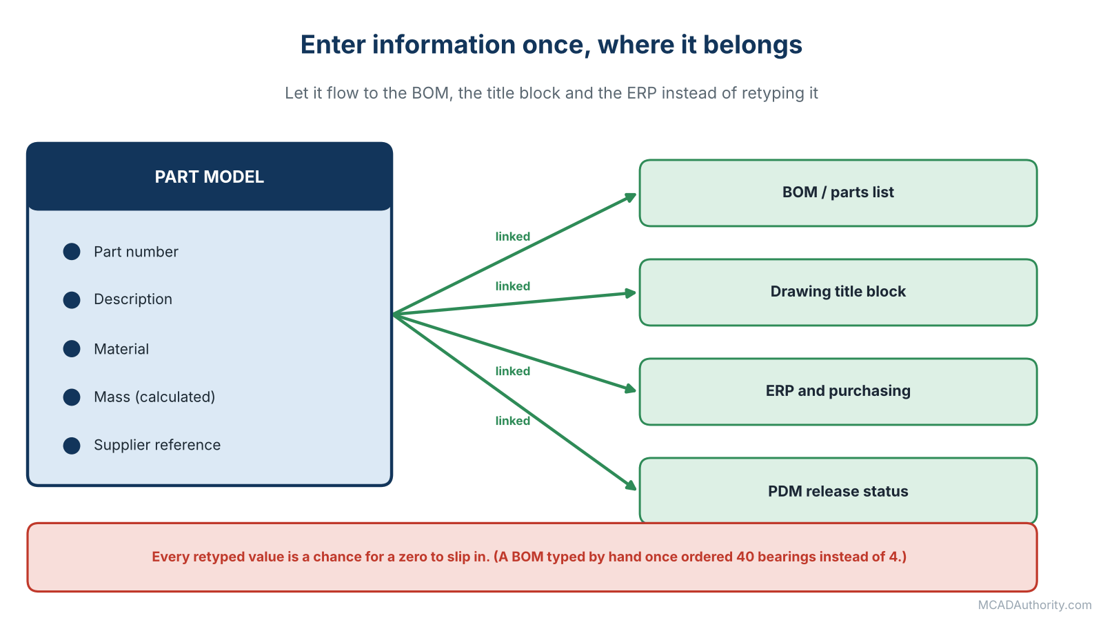
Figure 5. Enter information once and let it flow.
| Information | Best home | Reason |
|---|---|---|
| Shape and dimensions | Part model | Single source of geometry |
| Material | Part model (property) | Flows to BOM and drawing automatically |
| Mass | Calculated from part and material | Never typed manually |
| Part number and description | Part properties | Feeds BOM, title block and data management |
| Quantity | Assembly structure | Counted from component instances |
| How parts fit together | Assembly constraints | Reflects real relationships |
| Tolerances and notes | Drawing (or model annotations) | The manufacturing contract |
| Supplier and manufacturer data | Part properties and ERP | Used for purchasing |
| Revision and approval status | PDM system | Controlled and traceable |
| Cost | ERP or product data system | Changes over time, not a geometric property |
The rule behind this table is a simple one: enter information once, in the place where it belongs, and let it flow to everywhere else. Every time someone retypes a value, you create an opportunity for error.
How the Four Stay Consistent
Consistency is not automatic. It requires design, discipline and, ideally, a data management system.
Technical foundations
- Properties linked to title blocks and BOMs, so part numbers and descriptions are never retyped.
- Associative drawings, so views and dimensions follow the model.
- BOMs generated from assemblies, not built separately.
- Templates with the right property fields and drawing layouts. See Best Practices for Creating Mechanical CAD Templates.
- Controlled libraries of standard components.
Process foundations
- A written release procedure that includes a consistency check among part, assembly, drawing and BOM.
- A data management system that locks released files and tracks revisions. See Product Data Management (PDM): A Complete Guide.
- Change control that updates all affected documents together. See Engineering Change Requests (ECR) and Engineering Change Orders (ECO).
- Reviews with a checklist. See Mechanical CAD Model Review and Quality Assurance Checklist.
The pre-release consistency check I use
Before anything is released, I ask these questions.
- Do all parts have a material, part number and description?
- Does the assembly open without missing references or unresolved constraints?
- Does the interference check show only intended contacts?
- Does the BOM total match what I expect to build?
- Do the balloons on the assembly drawing match the BOM item numbers?
- Do part drawings show the same revision as the models?
- Are standard and purchased components flagged correctly?
- Are consumables and bulk items included?
- Are title block fields filled from properties, not typed?
- Is every released document in the vault at the right revision?
If any answer is “no” or “I don’t know”, the release waits.
Common Mistakes (And How They Happen)
- BOM typed by hand. The classic. Fix: generate it from the assembly.
- Part numbers that change meaning. Using “smart” numbers that encode size or material, then changing the size. Fix: simple, permanent numbers. See Mechanical CAD File Naming and Part Numbering Standards.
- Hidden components. Parts suppressed or hidden in the assembly that still need to be bought. Fix: check BOM settings and virtual components.
- Duplicate parts under different numbers. The same bracket created twice. Fix: library discipline and searching before creating.
- Drawings that show a different revision than the model. Fix: controlled release.
- Assemblies with no structure. Everything in one level. Fix: plan the hierarchy.
- Too much detail in purchased components. A motor model that is 80 MB of unnecessary geometry. Fix: simplified representations.
- Quantities that depend on pattern or configuration errors. A patterned fastener counted wrongly. Fix: always verify BOM counts against what you expect.
- Treating the drawing as an afterthought. The model is perfect, the drawing is a mess. Fix: plan drawing needs early, since they shape the dimensioning scheme.
- No one owns consistency. Fix: assign responsibility, for example to a CAD manager or reviewer.
If you hit technical trouble with these items, Mechanical CAD Troubleshooting: A Complete Guide gives practical remedies.
Who Reads What: A Quick Reference
Understanding your readers makes you a better author.
- Machinist or CNC programmer: reads the part drawing and often the 3D model. Needs clear datums, tolerances, finishes and notes.
- Sheet metal shop: reads the drawing and flat pattern. Needs material, thickness, bend radii, finishes.
- Welder or fabricator: reads weldment drawings with weld symbols and cut lists.
- Purchasing: reads the parts-only BOM. Needs supplier references and quantities.
- Production planner: reads the structured BOM. Needs sub-assemblies and sequence.
- Assembler: reads assembly drawings, exploded views and instructions.
- Quality inspector: reads drawings and tolerances to plan measurements.
- Service technician: reads exploded views and spare parts lists.
- Customer or auditor: reads specification, drawings and sometimes the model.
When I review someone’s work, I often ask: “Which of these people will be most confused by this?” The answer usually points to the weakest part of the package.
How This Is Changing (And What Is Not)
Technology is slowly reshaping these four deliverables. Cloud systems keep parts, assemblies and drawings together in one managed space. Model-based definition reduces dependence on drawings. Automation generates drawings and BOMs from rules. Digital thread concepts link design data to manufacturing and service. These ideas are discussed in Mechanical CAD Automation: A Complete Guide and Building a Digital Thread from Mechanical CAD to Manufacturing.
But the underlying logic is stable. You still need to define what each component is, how components fit together, how things must be made and what must be bought. Whatever the formats and tools of the future, those four questions will stay.
A Practice Exercise
To make the connections concrete, try this on any MCAD system.
- Model three simple parts: a base plate, a vertical bracket and a pin.
- Assign materials and properties, including part numbers and descriptions.
- Create an assembly with the plate, two brackets, and four standard screws from the library.
- Run an interference check and fix any problems.
- Generate a BOM in both structured and parts-only views.
- Create drawings: one for the plate, one for the assembly with balloons and a parts list.
- Change a part: make the plate 20 mm longer. Watch what updates.
- Compare the model, drawing and BOM. Do they all agree?
- Add a consumable, such as thread-locking adhesive, as a virtual component, and see how it appears in the BOM.
For a more guided progression, see Mechanical CAD Practice Exercises for Beginners.
Final Thoughts
That pallet of forty bearings sat in a corner of the stockroom for years, and whenever I walked past it, I thought: the machine was designed beautifully, and a single unmanaged number beat it. Excellent parts, perfect assemblies and flawless drawings are not enough if the information that connects them is not controlled.
Think of your design as one body of knowledge expressed in four forms. Keep it in one place, build it carefully and let the software transmit it, rather than retyping it. If you do, you will spend less time chasing mistakes and more time designing.
Where to go next: you now have the foundations of Category A. Continue into the technical guides with Parametric 3D Modeling: A Complete Practical Guide for part modeling, Assembly Modeling in Mechanical CAD: A Complete Guide for assemblies, and Mechanical Engineering Drawings: A Complete Guide for documentation.