
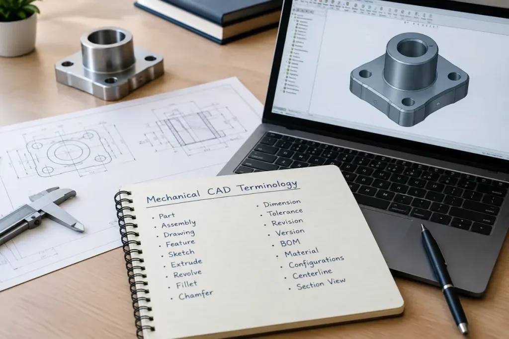

In my first week on any new team, I run a small, slightly mischievous experiment. I ask three people the same question: “What is the difference between a version and a revision?” It is rare to get three identical answers. In one case, a design manager and a senior designer spent ten minutes arguing about it while the junior who had asked the original question quietly took notes. The argument ended only when we looked at a drawing that had been manufactured twice, to two different “latest versions”.
Words matter in engineering. A misunderstood term becomes a misunderstood requirement, and a misunderstood requirement becomes a scrapped part. Learning the vocabulary of Mechanical CAD is not academic work; it is risk management. It also makes you faster, because you can read documentation, follow tutorials, talk to suppliers and ask for help without constantly stopping to decode jargon.
This guide gives you the essential vocabulary of MCAD, grouped by subject, with short definitions and, where useful, my own practical comment. I have included the terms you will meet daily, the ones that cause confusion, and a table showing how the same idea is named in different software systems. If you are new to the field, start with What Is Mechanical CAD (MCAD)? A Complete Beginner’s Guide, then keep this page open as a reference.
How to Use This Glossary
You do not need to memorize it. Read it once through, to get a feel for the landscape, then return to a section when you need it. Terms are grouped as follows:
- The big acronyms
- Sketching
- Features and modeling
- Geometry and data representation
- Assemblies
- Drawings and documentation
- Tolerances and fits
- Manufacturing terms
- Simulation terms
- Files, data and change management
At the end you will find a comparison of terms across popular systems, and a short list of the confusions I see most often.
1. The Big Acronyms
- CAD (Computer-Aided Design): using software to create and document designs. The umbrella term.
- MCAD (Mechanical CAD): CAD for mechanical products: parts, machines, mechanisms and tools. See Mechanical CAD vs. General-Purpose CAD: Key Differences Explained.
- ECAD (Electronic or Electrical CAD): CAD for circuits, boards and wiring.
- AEC / BIM (Architecture, Engineering, Construction / Building Information Modeling): CAD and data modeling for buildings and infrastructure.
- CAM (Computer-Aided Manufacturing): software that generates machine instructions, such as CNC toolpaths, from a CAD model. See CAD to CAM: Understanding the Complete Manufacturing Workflow.
- CAE (Computer-Aided Engineering): analysis and simulation tools: stress, heat, flow, vibration, motion. See Computer-Aided Engineering (CAE): A Complete Beginner’s Guide.
- PDM (Product Data Management): controlled storage, versioning and release of engineering files. See Product Data Management (PDM): A Complete Guide.
- PLM (Product Lifecycle Management): the broader management of product information across its whole life: requirements, design, manufacturing, service. See PDM vs. PLM: Understanding the Key Differences.
- BOM (Bill of Materials): the structured list of parts, quantities and materials that make up a product. See Understanding Parts, Assemblies, Drawings, and BOMs in MCAD.
- DFM / DFA (Design for Manufacturing / Design for Assembly): design principles that make parts easy to produce and assemble. See Design for Manufacturing (DFM) and Design for Assembly (DFA): A Complete Guide.
- MBD (Model-Based Definition): defining a product’s requirements directly in the 3D model, with annotations, instead of relying only on drawings.
- PMI (Product Manufacturing Information): the dimensions, tolerances, notes and symbols attached to a 3D model. See Model-Based Definition (MBD) and 3D Product Manufacturing Information (PMI).
- GD&T (Geometric Dimensioning and Tolerancing): a symbolic language for defining the allowed variation of form, orientation and position. See Geometric Dimensioning and Tolerancing (GD&T): A Complete Guide.
- FEA (Finite Element Analysis): a numerical method for predicting how a part behaves under load, heat or vibration.
- CFD (Computational Fluid Dynamics): simulation of liquid and gas flow.
- ECR / ECO (Engineering Change Request / Order): the formal documents requesting and authorizing a change to a released design. See Engineering Change Requests (ECR) and Engineering Change Orders (ECO).
2. Sketching
Nearly every 3D shape starts here.
- Sketch: a 2D drawing made on a plane or face, used as the basis for a feature.
- Profile: a closed outline in a sketch, used to create a solid. A sketch with gaps will not produce a solid.
- Sketch plane: the flat surface on which a sketch is drawn.
- Geometry (sketch entities): the lines, arcs, circles, splines and points in a sketch.
- Construction geometry: helper elements, such as centerlines, that guide the sketch but do not create material.
- Dimension: a numerical size or position that controls geometry.
- Driving dimension: a dimension that controls the geometry. Change the number, the shape changes.
- Driven (reference) dimension: a dimension that only reports a value and cannot be edited. Useful for checking.
- Constraint (geometric relation): a rule linking geometry: horizontal, vertical, parallel, perpendicular, tangent, concentric, coincident, equal, symmetric, fixed.
- Degrees of freedom (DOF): the ways a sketch element can still move. A fully constrained element has none left.
- Fully defined (fully constrained) sketch: nothing can move without changing a dimension. This is the professional standard.
- Under-defined sketch: some geometry is still free to move. Risky, because it may shift when edited.
- Over-defined sketch: too many dimensions or constraints, some conflicting. The software warns you.
- Projected geometry: edges or sketches from other features, projected into the current sketch as references.
- Solver: the engine that calculates sketch geometry from dimensions and constraints.
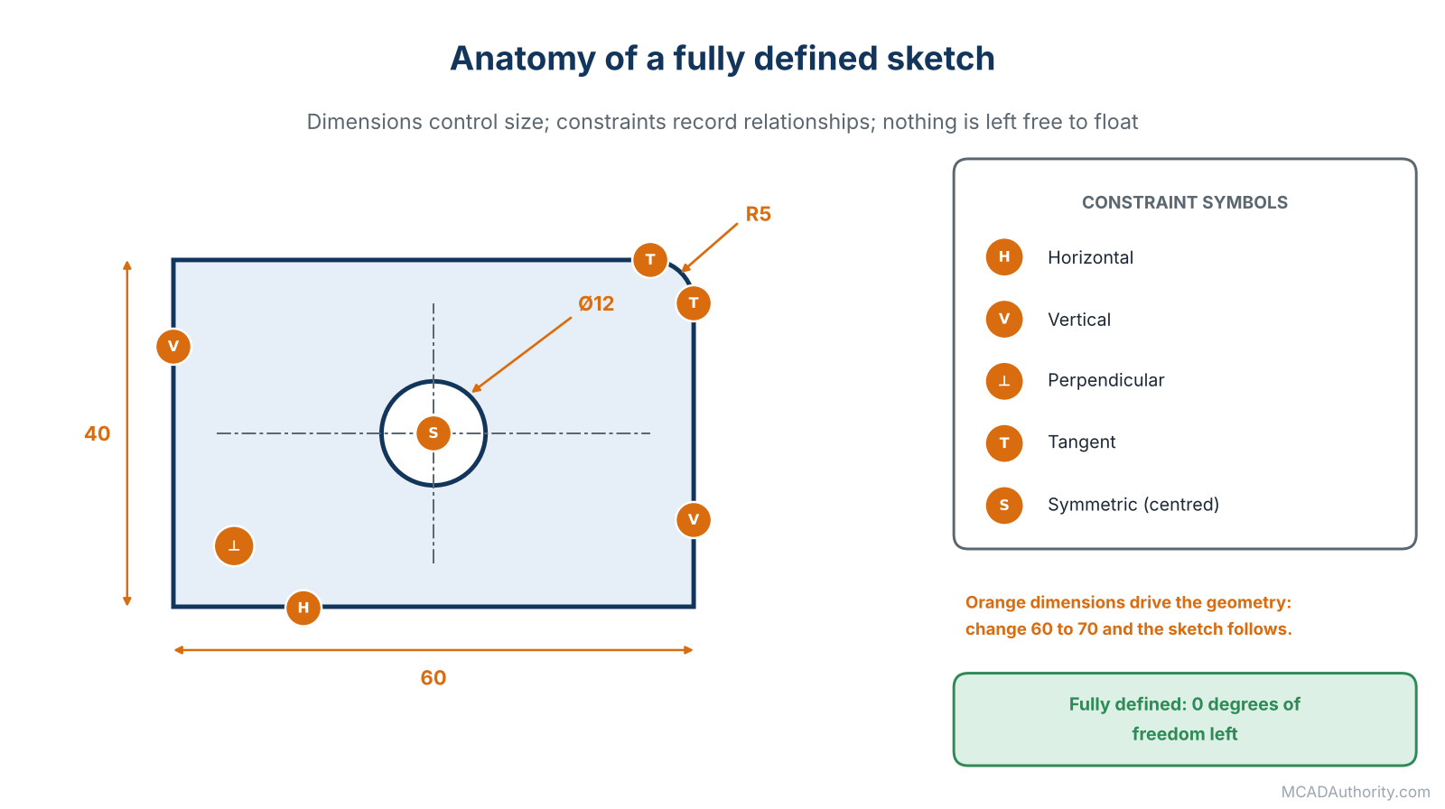
Figure 1. Anatomy of a fully defined sketch.
My comment: the habit of making every sketch fully defined is the cheapest quality improvement I know. For help when it goes wrong, see Resolving Overdefined and Underdefined Sketches.
3. Features and Modeling
- Feature: a single modeling operation that adds or removes material, or modifies a shape.
- Base feature: the first feature in a part, from which everything else grows.
- Extrude: pushes a sketch profile straight, giving it thickness. Can add (boss) or remove (cut) material.
- Revolve: spins a profile around an axis. Used for shafts, pulleys, bottles and any round part.
- Sweep: moves a profile along a path, producing tubes, rails or pipes.
- Loft: blends between two or more profiles, producing transitions and organic shapes.
- Hole (hole feature): a purpose-built operation that creates a hole with defined diameter, depth, thread and type. Better than a plain cut because it carries meaning.
- Fillet: rounds an edge. Chamfer: bevels an edge.
- Shell: hollows a solid, leaving walls of a chosen thickness. Common in castings, molded parts and enclosures.
- Draft: a small taper applied to faces so a molded or cast part can be released from its mold.
- Rib and boss: reinforcing and mounting features common in plastic and cast parts.
- Pattern: repeats a feature: linear, circular or along a path.
- Mirror: copies a feature or body across a plane.
- Boolean operations: combining solids by joining (union), cutting (subtraction) or intersecting.
- Body: a distinct solid within a part file. A part may contain several (multi-body modeling).
- Parametric modeling: a method where geometry is driven by dimensions, constraints and a history of features. See Parametric 3D Modeling: A Complete Practical Guide.
- Direct modeling: editing the geometry itself, by pushing and pulling faces, without relying on history. See Parametric vs. Direct Modeling: Which Approach Is Better?
- Feature tree (model tree, browser, timeline): the ordered list of features that built a part. Different software names it differently.
- History: the recorded sequence of operations. Reading it tells you how a part was made.
- Parent-child relationship: a dependency between features. A fillet is the child of the edge it rounds. Delete the parent and the child may fail.
- Rollback: temporarily returning the model to an earlier point in its history, to edit or insert a feature.
- Suppress: temporarily switching a feature off, without deleting it.
- Rebuild (regeneration, update): recalculating the model after an edit.
- Failed feature: a feature that cannot be rebuilt because its references are missing or its geometry is invalid. See How to Fix Failed Features in Parametric CAD Models.
- Design intent: the rules and reasoning that define how the model should behave when changed. See Understanding Design Intent in 3D Mechanical Modeling.
- Parameter: a named value, such as a length or count, that controls a model.
- Equation (formula): a relationship between parameters, such as a boss diameter equal to the hole diameter plus twice the wall thickness.
- Configuration / family table / design table: a method of defining multiple variants of a part or assembly in a single file. Autodesk Inventor uses iParts and iAssemblies for similar purposes. See Design Tables and Parameter-Driven CAD Models.
- Template: a starting file with preset units, materials, standards and layouts.
- Origin: the point where the model’s coordinate axes meet. Good models are anchored to it.
- Reference geometry (work features, datum features): planes, axes and points used to position other features. In Autodesk Inventor, these are called work planes, work axes and work points.
- Coordinate system: a set of axes used to locate geometry, often needed for manufacturing and analysis.
4. Geometry and Data Representation
This is the “what’s under the hood” section. You can design for years without knowing it, but understanding it explains many strange behaviors.
- Wireframe model: edges only, no surfaces or volume.
- Surface model: infinitely thin skins describing the outside of an object. See Surface Modeling in Mechanical CAD: A Complete Guide.
- Solid model: a closed volume with an inside and an outside, which therefore has mass and can be cut, assembled and analyzed.
- Mesh model: a shape made of many small triangles or polygons, typical of 3D scans and STL files. See B-Rep vs. Mesh Geometry: Understanding the Differences.
- B-rep (boundary representation): the way most solid modelers store geometry: as a collection of faces, edges and vertices that bound a volume.
- Face, edge, vertex: the surfaces, curves and points that make up a B-rep solid.
- NURBS (Non-Uniform Rational B-Splines): the mathematical curves and surfaces used to describe free-form shapes.
- Geometry kernel: the mathematical engine that creates and manipulates solids. Well-known kernels include Parasolid and ACIS. Autodesk’s products use a kernel called ShapeManager, which evolved from ACIS. See Parasolid vs. ACIS: Understanding 3D Geometry Kernels.
- Manifold / watertight: a valid solid with no gaps, no overlapping faces and a well-defined inside. Non-manifold geometry is a common cause of import and printing problems.
- Tessellation: converting smooth geometry into a mesh of triangles for display, printing or analysis.
- Tangent continuity (G1) and curvature continuity (G2): descriptions of how smoothly two surfaces meet. G0 means they simply touch; G1 means no visible crease; G2 means the curvature also matches. See Understanding Curvature Continuity: G0, G1, G2, and G3.
- Dumb solid: a solid with no feature history, typically imported from another system. It can be edited directly, but its original intent is lost.
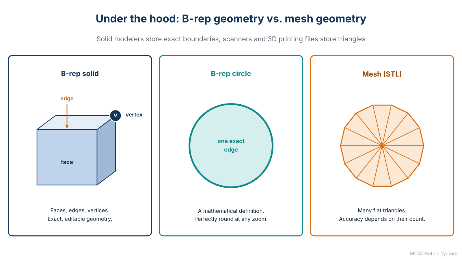
Figure 2. B-rep stores exact boundaries; a mesh approximates shapes with triangles.
5. Assemblies
- Part: a single component, typically a single manufactured item.
- Subassembly: an assembly that is itself used inside a larger assembly.
- Assembly: a collection of parts and subassemblies positioned relative to each other.
- Component: any part or subassembly placed in an assembly. Also called an occurrence or instance in some systems.
- Constraint (mate, joint): a relationship between two components that defines how they are positioned. In Inventor and Creo, the term is constraint; in SOLIDWORKS, mate; in Fusion, joint. A joint may also include motion. See Understanding Assembly Constraints, Mates, and Joints.
- Grounded (fixed) component: a component locked in space, used as the reference for the rest of the assembly.
- Degrees of freedom (assembly): the motions a component can still make. Free components have six: three translations and three rotations. See Degrees of Freedom in Mechanical Assemblies Explained.
- Interference: two components occupy the same space. Interference checking finds them automatically. See Interference Detection and Clearance Analysis in MCAD.
- Clearance: the gap between components. Too little causes collisions; too much causes looseness.
- Bottom-up design: creating parts individually, then assembling them.
- Top-down design: defining the overall layout first, and creating or driving parts from it. See Bottom-Up vs. Top-Down Assembly Design.
- Skeleton (master layout): a sketch or simple model that controls the positions and sizes of many parts. See Skeleton Modeling and Master Layout Techniques.
- In-context design (external reference): a part created or driven using the geometry of other parts within an assembly.
- Exploded view: an image or animation showing components separated along their assembly paths.
- Representation (display state, configuration of view): a saved way of displaying an assembly, for example with some parts hidden or simplified. Large assemblies use simplified or lightweight representations to remain responsive. See How to Create and Manage Large CAD Assemblies.
- Envelope: a simplified volume representing the maximum space a part or module may occupy.
- Standard (library) component: a purchased or standardized item such as a screw, bearing or pin. See Managing Standard Parts and CAD Component Libraries.
6. Drawings and Documentation
- Engineering drawing: the formal 2D document describing a part or assembly for manufacturing or assembly. See Mechanical Engineering Drawings: A Complete Guide.
- Orthographic projection: representing a 3D object with flat views (front, top, side) taken along perpendicular directions.
- First-angle and third-angle projection: two conventions for arranging those views. First-angle is common in Europe and much of the world; third-angle in North America. See Orthographic Projection and Engineering Drawing Views Explained.
- Base view / projected view: the first view you place, and the views derived from it.
- Section view: a view showing the inside of a part, as if it had been cut open.
- Detail view: an enlarged view of a small area.
- Auxiliary view: a view taken perpendicular to an inclined face, to show its true shape.
- Broken view: a view with the middle removed, to shorten long parts.
- Associative: a drawing is associative when it updates automatically with changes to the model.
- Title block: the box on a drawing that holds part number, title, material, scale, author, date and revision.
- Revision block (revision table): the record of each approved change on the drawing.
- Balloon (item number): a numbered callout linking a component in the drawing to its row in the parts list.
- Parts list: the table on an assembly drawing listing the components. Generated from the BOM.
- Scale: the ratio between drawing size and actual size.
- Annotation: any note, symbol, dimension or text added to a view.
- Dimensioning: the practice of specifying sizes and positions. See Engineering Dimensioning: Rules and Best Practices.
- Hole table: a table listing sizes and positions of holes, often used on plates.
- Datum (drawing): a reference surface, axis or point that dimensions and tolerances are measured from.
7. Tolerances and Fits
- Nominal size: the theoretical size of a feature, such as 25 mm.
- Tolerance: the permitted variation from nominal. A dimension of 25 plus or minus 0.1 mm may range from 24.9 to 25.1.
- Limits: the maximum and minimum permitted sizes.
- Fit: the relationship between two mating parts, such as a shaft in a hole. It may be a clearance fit (always a gap), an interference fit (always tight) or a transition fit (either). See Fits and Tolerances: Clearance, Transition, and Interference Fits.
- Tolerance stack-up: the accumulation of tolerances across several parts or features, affecting whether an assembly fits. See Tolerance Stack-Up Analysis for Mechanical Assemblies.
- General tolerances: default tolerances stated in a note or title block for dimensions without specific ones.
- Datum (GD&T): a theoretical reference defined by a real feature, used as the starting point for geometric tolerances. See Datums and Datum Reference Frames in Mechanical Design.
- Feature control frame: the rectangular symbol that states a geometric tolerance, its value and its datum references. See Understanding GD&T Symbols and Feature Control Frames.
- Surface finish (roughness): the texture of a surface, specified by symbols and values. See Surface Finish and Surface Roughness Symbols Explained.
- ASME Y14.5 and ISO GPS: the main standards families for dimensioning and tolerancing. See ASME Y14.5 vs. ISO GPS: Understanding the Differences.
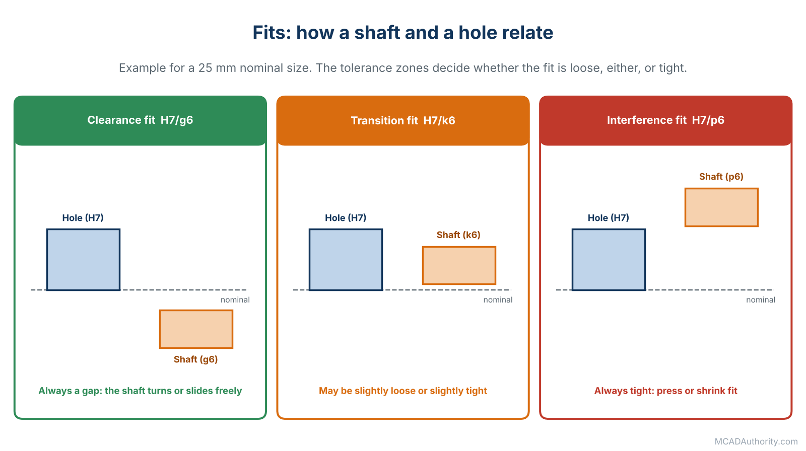
Figure 3. Clearance, transition and interference fits compared.
8. Manufacturing Terms
- CNC (Computer Numerical Control): machine tools controlled by programmed instructions, such as milling machines and lathes.
- Toolpath: the path a cutting tool follows to machine a part.
- Post-processor: software that translates toolpaths into the specific code format of a particular machine.
- Milling and turning: machining by rotating cutters over a stationary part, and by rotating the part against a stationary tool.
- Sheet metal: parts made from flat metal sheet, cut and bent.
- Flat pattern: the unfolded shape of a bent sheet metal part, used for cutting.
- Bend allowance and K-factor: values used to compute how much material a bend consumes. The K-factor describes where the neutral line sits within the thickness. See Understanding Bend Allowance, Bend Deduction, and K-Factor.
- Weldment: an assembly of parts joined by welding, typically frames and structures. See Weldment Design and Modeling in Mechanical CAD.
- Casting and injection molding: forming parts by pouring or injecting material into a mold.
- Parting line: the line where mold halves meet.
- Undercut: a feature that prevents a part from being released from a simple two-part mold or accessed by a cutter.
- Wall thickness: the thickness of the walls of a molded, cast or hollow part. Uniformity is usually the goal.
- Additive manufacturing (3D printing): building parts layer by layer. See Design for Additive Manufacturing (DfAM): A Complete Guide.
- Jig and fixture: devices that hold or guide a workpiece during manufacturing or inspection. See Designing Jigs, Fixtures, and Manufacturing Tooling.
- Prototype: an early physical version, used to test form, fit or function.
- First article: the first production part, inspected in detail against the drawing.
9. Simulation Terms
- Mesh: the network of small elements into which a model is divided for analysis.
- Element: a small piece of the mesh, such as a tetrahedron or hexahedron.
- Mesh convergence: refining the mesh until the results stop changing significantly. See Understanding Mesh Generation and Mesh Convergence in FEA.
- Load: a force, pressure, torque, temperature or other action applied to a model.
- Constraint (fixture, support) in simulation: a condition that holds the model in place. Note that this word means something different from an assembly constraint.
- Boundary conditions: the full set of loads and supports. See Loads, Constraints, and Boundary Conditions in Mechanical Simulation.
- Stress: internal force per unit area.
- Von Mises stress: a combined stress value commonly used to judge whether ductile materials will yield.
- Strain and deformation (displacement): how much a part stretches or moves under load.
- Factor of safety: the ratio between material strength and applied stress.
- Modal analysis: finding the natural frequencies and shapes of vibration of a structure.
- Kinematics: studying motion without considering forces. Dynamics includes forces.
- Topology optimization and generative design: methods that propose shapes by removing material that carries little load. See Topology Optimization and Generative Design in Mechanical Engineering.
10. Files, Data and Change Management
- Native file: a file in the software’s own format, such as
.iptand.iamin Autodesk Inventor, or.sldprtand.sldasmin SOLIDWORKS. - Neutral file: a file in a vendor-independent format, such as STEP, IGES, STL, DXF or 3MF. See Native vs. Neutral CAD File Formats: Advantages and Risks.
- STEP: a widely used international standard for exchanging 3D product data. See STEP Files Explained: Uses, Advantages, and Limitations.
- STL: a mesh format used mainly for 3D printing. See STL vs. STEP vs. 3MF: Choosing the Right 3D File Format.
- DWG and DXF: drawing file formats, originating in AutoCAD and widely supported.
- Metadata (properties): information attached to a file: part number, description, material, author, revision.
- Part number and item number: the part number identifies the part uniquely across the company. The item number is the line position in one particular BOM. They are not the same.
- Check-in / check-out: taking a file from the vault to edit and returning it. Prevents two people from overwriting each other.
- Vault: the secure repository managed by a PDM system. Autodesk Vault is a well-known example.
- Version: one saved state of a file. Versions accumulate during work.
- Revision: a formally released and approved state, usually labeled A, B, C or 1, 2, 3. See CAD Version Control vs. Revision Control Explained.
- Released / in work / obsolete: common lifecycle states for documents.
- Where used / contains: relationships showing which assemblies use a part, or which parts an assembly includes.
- Engineering BOM and Manufacturing BOM (EBOM and MBOM): the BOM as the designer sees it, versus the BOM as production builds it. See Engineering BOM vs. Manufacturing BOM: Key Differences.
- Digital thread: the continuous link of data from design through manufacturing and service. See Building a Digital Thread from Mechanical CAD to Manufacturing.
Same Idea, Different Names: A Cross-Software Table
Moving between systems is easier when you realize that the concepts are shared and only the labels change. Here is a quick comparison for popular systems. Exact names can differ between versions, so treat this as an orientation.
| Concept | Autodesk Inventor | Autodesk Fusion | SOLIDWORKS | PTC Creo | Siemens NX |
|---|---|---|---|---|---|
| History list | Model browser | Browser and timeline | FeatureManager design tree | Model tree | Part navigator |
| Part file | .ipt |
Design in the cloud (.f3d) |
.sldprt |
.prt |
.prt |
| Assembly file | .iam |
Design with components | .sldasm |
.asm |
.prt (assembly) |
| Drawing file | .idw or .dwg |
Drawing | .slddrw |
.drw |
Drawing in .prt |
| Assembly relationship | Constraint, joint | Joint | Mate | Constraint | Assembly constraint |
| Variants | iPart, iAssembly, parameters | Parameters, configurations | Configurations, design tables | Family tables | Part families, expressions |
| Reference geometry | Work plane, axis, point | Construction plane, axis, point | Reference plane, axis, point | Datum plane, axis, point | Datum plane, axis, point |
| Sheet metal | Sheet Metal environment | Sheet metal | Sheet metal | Sheet metal | Sheet metal |
| Welded structures | Frame Generator, weldment | Limited, via add-ons | Weldments | Frame and weld tools | Structural and weld tools |
| Data management | Autodesk Vault | Cloud-based project and data management | SOLIDWORKS PDM | Windchill | Teamcenter |
If you are choosing or comparing systems, see Best Mechanical CAD Software for Professional Engineers and How to Migrate from One Mechanical CAD System to Another.
The Confusions I See Most Often
Having trained many classes, I can predict which pairs of terms will cause trouble.
- Version vs. revision. A version is a save. A revision is a formal, approved issue. A part may have forty versions and be on revision B.
- Part number vs. item number. One identifies the part, the other the row in a BOM.
- Constraint (sketch) vs. constraint (assembly) vs. constraint (simulation). Same word, three meanings: a geometric rule in a sketch, a positional relationship between components, and a support in an analysis.
- Datum (CAD reference) vs. datum (GD&T). One is a plane or axis used for modeling; the other is a reference on the real part used for tolerancing.
- Assembly vs. subassembly. Often the same file type, only the role differs.
- Parametric vs. direct. Not opposites. Many systems use both.
- Model vs. drawing. The model is the master. The drawing is a report derived from it, and also the contractual document in many industries.
- Tolerance vs. fit. A tolerance is for one feature. A fit is the relationship between two features.
- Native vs. neutral. Neutral formats lose some information, particularly history and intent.
- Configuration vs. revision. A configuration is a variant that coexists. A revision is a replacement over time.
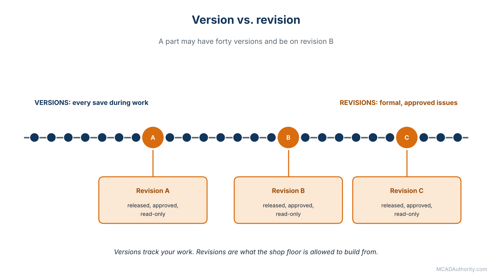
Figure 4. Versions track your work; revisions are the formal releases.
A Short Learning Strategy for Vocabulary
If you want the terminology to stick, here is what has worked for my students.
- Learn terms in context. When you build your first part, name each concept as you use it.
- Read real drawings. Ask a machinist or a supplier to show you drawings from the shop floor.
- Keep a personal glossary. Add terms as you meet them, with an example from your own work.
- Ask what the term means in your company. Many teams use local variants of words. Write the local definition down.
- Teach someone else. Explaining a term is the best test of whether you understand it.
- Respect the standards. Where a term is defined in ASME or ISO documents, the standard is the authority. See Mechanical CAD Standards: A Complete Guide.
Final Thoughts
I sometimes tell my trainees that CAD is two languages at once. One is the language of the software: buttons, menus and commands that change every year. The other is the language of engineering: features, tolerances, fits, datums and revisions that have barely changed in decades. Learn the second one deeply, and the first one will always be learnable.
Use this glossary as a map, not a test. Return to it whenever a term trips you up. And when someone on your team uses a word differently from you, do not argue; write the definition down and agree on it. That small act will prevent more errors than any software feature.
Where to go next: continue with Understanding Parts, Assemblies, Drawings, and BOMs in MCAD, which shows how the four core deliverables relate, and then The Complete Mechanical CAD Workflow: From Concept to Manufacturing to see these terms in a real project sequence.