

Every few years, the CAD world rediscovers an old argument and treats it as news. Right now the argument is parametric versus direct modeling. I have watched it play out in vendor presentations, in user forums and, most memorably, in a heated meeting where a design manager declared that “history-based modeling is dead” while the senior designer beside him quietly kept updating forty product variants by changing a single table.
Both of them were right, and both were wrong. The honest answer to “which is better?” is the one every experienced CAD manager eventually gives: it depends on what you are doing, who will edit it later, and what you expect to change. In this guide I will explain exactly how each approach works, what each one costs you, and how to decide, with practical examples drawn from real design offices and from the tools I teach, including Autodesk Inventor and Fusion.
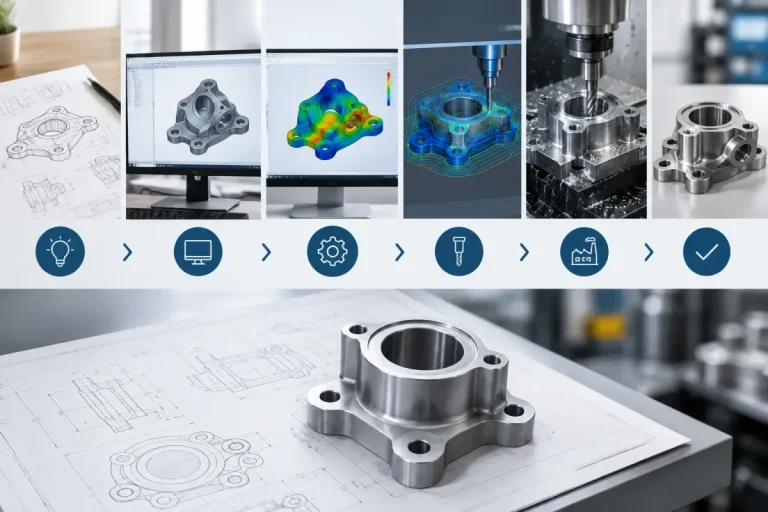
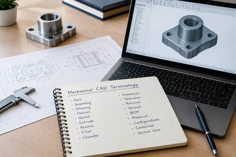
If you are new to the vocabulary, begin with What Is Mechanical CAD (MCAD)? A Complete Beginner’s Guide and Essential Mechanical CAD Terminology Every Designer Should Know.
The Short Answer
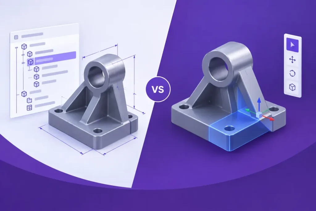
- Parametric modeling builds a part as a recorded sequence of features driven by dimensions, constraints and relationships. You change the parameters and the model rebuilds.
- Direct modeling edits the geometry itself, by pushing, pulling, moving and rotating faces, without relying on a recorded history.
Parametric is best when you design families, variants and controlled products that will evolve. Direct is best when you need speed and freedom, or when you work with geometry that has no history, such as imported files.
And the practical answer today is that most mature systems offer both, which means your real skill is knowing when to switch.
What Parametric Modeling Really Is
The word parametric means that the shape is controlled by parameters: named values such as lengths, angles, counts and conditions. But in practice, when people say parametric modeling they mean a complete way of working with four ingredients.
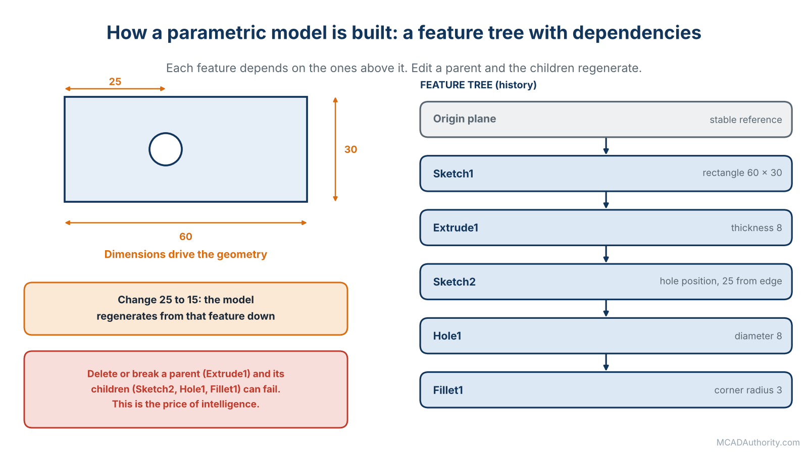
Figure 1. A parametric model is a chain of dependent features driven by dimensions.
1. Sketches with dimensions and constraints
You draw a profile, then you define it with dimensions (this edge is 60 mm) and geometric constraints (this line is tangent to that arc, these two circles are equal). A fully defined sketch has no remaining freedom, so it behaves predictably. The solver inside the software recalculates the sketch whenever a value changes.
2. Features in a recorded order
You turn the sketch into a feature: extrude, revolve, sweep, hole, fillet, pattern. Each feature is added to a history, shown as a tree or timeline: the model browser in Inventor, the FeatureManager in SOLIDWORKS, the timeline in Fusion. The order matters, because each feature builds on the ones before it.
3. Dependencies between features
Later features depend on earlier ones. A fillet depends on the edge it rounds. A hole depends on the face it is placed on. These parent-child relationships are what make the model rebuild intelligently, and they are also what can make it break.
4. Formulas, parameters and tables
You can link dimensions with equations (a flange thickness equal to one tenth of the diameter), name parameters, and drive many sizes from a spreadsheet or design table. This is how one model becomes a whole product family. See Design Tables and Parameter-Driven CAD Models.
What happens when you edit
When you change a dimension, the software regenerates the model from the edited feature onward, recalculating every dependent feature in order. It is a bit like a recipe: change the quantity of flour at step two and every later step adjusts.
Where parametric shines
- Design intent is captured. Relationships such as “this hole is always centered” or “this wall is always 3 mm” live in the model. See Understanding Design Intent in 3D Mechanical Modeling.
- Predictable change. Edit a value, get a controlled result.
- Families and configurations. Dozens of sizes from one model.
- Automation. Rules, scripts and configurators can drive parameters. See Mechanical CAD Automation: A Complete Guide.
- Traceability. You can read the history to understand how a part was built.
- Consistency across teams. With standards in place, anyone can open and understand a model.
Where parametric hurts
- Planning is required. A badly planned feature order creates fragile models.
- Failures cascade. Delete or change a parent and children can fail. How to Prevent Feature Failures in Parametric CAD Models and How to Fix Failed Features in Parametric CAD Models address this.
- Editing a stranger’s model can be slow. You must first understand the logic before you dare to change it.
- Imported geometry has no history. You cannot apply parametric thinking to a dumb solid from a supplier.
- Over-constrained models are rigid. Too many relationships make simple changes difficult.
- Heavier skill requirement. Beginners often build models that look right but behave badly.
What Direct Modeling Really Is
Direct modeling is a different mental model. Instead of asking “which dimension controls this?”, you simply grab the geometry and change it.
- Select a face and pull it to make a boss taller.
- Select a hole’s face and resize it by typing a new diameter.
- Select a group of faces and move them.
- Delete a feature’s faces and let the software heal the gap.
- Offset a face, rotate a face, replace one face with another.
There is no required sequence, because the software works on the final shape, not on a recorded recipe. A history-free or history-light system recognizes geometry such as holes, fillets and flat faces, and tries to preserve relationships like concentricity or tangency while you edit.
Where direct modeling shines
- Speed for exploration. Concepts can be shaped in minutes, without worrying about a feature tree.
- Freedom. No parent-child failures, because there are few dependencies.
- Imported geometry. A STEP file from a supplier or customer can be modified immediately. See Repairing Imported CAD Models: Common Problems and Solutions.
- Preparing models for other uses. Simplifying a model for simulation by removing small features, or adapting a model for tooling, is quick.
- Lower learning curve. Many beginners find it more intuitive, because it resembles working with a physical object.
- Late changes. When an unplanned modification arrives on a Friday afternoon, a direct edit gets it done.
Where direct modeling hurts
- Design intent is not stored. The model remembers shape, not reasons. The next person has no way to know that a certain dimension is supposed to equal another.
- Changes do not propagate by rule. You edit one place, and you must remember to edit the related places.
- No family tables or automation. Variant generation is limited or impossible.
- Less traceability. You cannot read how the model was built.
- Larger risk of silent errors. Without relationships, a change can quietly violate a requirement.
- Weaker for complex controlled products. Large teams working on long-lived products usually need more structure.
Side-by-Side Comparison
| Criterion | Parametric (history-based) | Direct (history-free) |
|---|---|---|
| Basic idea | Edit the recipe, the model rebuilds | Edit the shape, the model adapts |
| Design intent | Stored in sketches, constraints and formulas | Mostly in the designer’s head |
| Speed of first model | Slower, requires planning | Faster, more intuitive |
| Speed of controlled change | Excellent when well built | Quick for single edits, slower for repeated variants |
| Variants and families | Natural strength | Weak |
| Automation | Strong | Limited |
| Imported geometry | Little help | Very strong |
| Risk of failure on edit | Higher (feature errors) | Lower |
| Risk of silent inconsistency | Lower | Higher |
| Learning curve | Moderate to steep | Gentle |
| Best for | Product families, controlled design, long-lived products | Concepts, imported data, quick modifications, simulation prep |
The Hybrid Reality: Most Systems Offer Both
The old argument is less sharp today, because the industry has largely converged. Here is the situation as I teach it, though specific commands and names change with each version.
- Autodesk Inventor is fundamentally parametric, and it also provides direct edit tools that let you move, resize and rotate faces of existing geometry, which is especially useful on imported models.
- Autodesk Fusion records a design history in a timeline, and you can also work without capturing history when you prefer a direct approach.
- SOLIDWORKS is parametric, with tools such as Move Face and Instant3D for direct-style edits.
- Siemens NX and Solid Edge offer synchronous approaches that combine history-free editing with parametric features.
- PTC Creo offers flexible modeling tools alongside its parametric core.
- Ansys SpaceClaim and Shapr3D are built primarily around direct modeling.
When you read vendor marketing, remember that “hybrid” does not mean you get the best of both worlds automatically. It means you get both toolsets in the same program, and you must decide how to use them in each situation.
The Same Change, Two Ways
Nothing clarifies this like a concrete example. Suppose you have a mounting bracket with a hole near one end, and the customer asks: move the hole 10 mm closer to the edge and make it 2 mm larger.
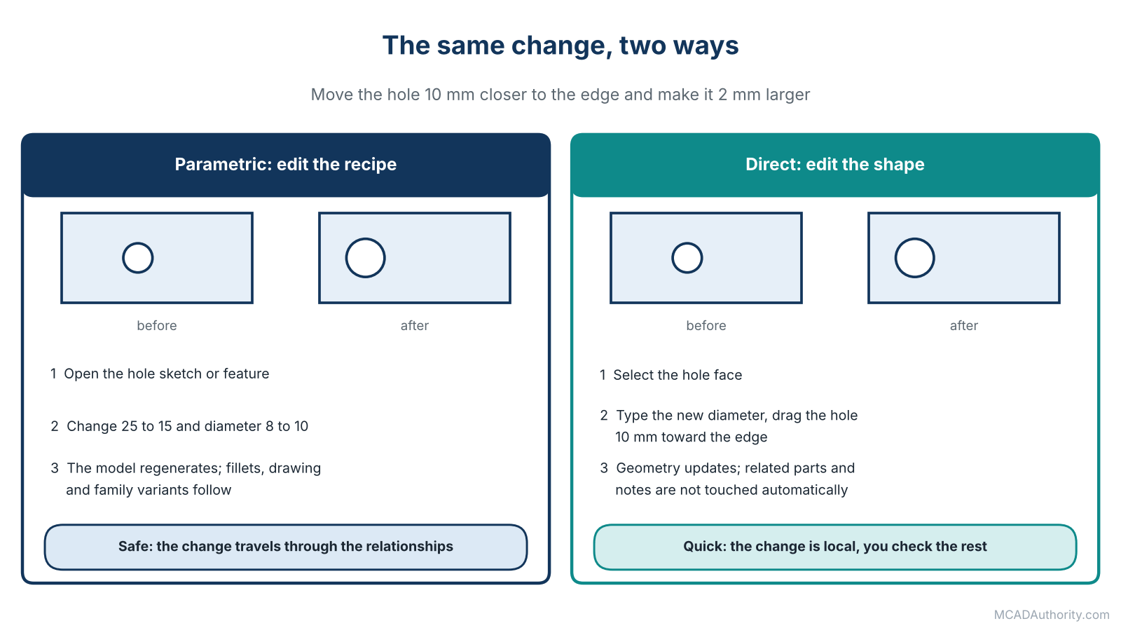
Figure 2. The same change made the parametric way and the direct way.
The parametric way
- You open the sketch that positions the hole (or the hole feature’s definition).
- You change the distance dimension from 25 mm to 15 mm, and the diameter from 8 to 10.
- The model regenerates. Because you built the fillet around the hole relative to the hole, it follows. Because the drawing is linked, it updates. Because a design table controls the bracket length, the family stays consistent.
If the model was built well, this takes thirty seconds and leaves nothing behind. If it was built badly, a downstream feature may fail and you spend ten minutes repairing it.
The direct way
- You select the hole face, type the new diameter, and drag or type the new position.
- The software moves the hole, maintains the surrounding faces where it can, and finishes.
This also takes thirty seconds, and it works whether or not the model has a history. But note what you did not do: you did not update the relationship with the surrounding fillet, the drawing note or the sister part in the assembly that expected this hole to be a certain distance from the edge. In a simple bracket, that does not matter. In a controlled product, it might.
The point is not that one is faster. The point is that parametric makes change safe, while direct makes change quick. Safety matters more as complexity, team size and product life increase.
When I Choose Parametric
From years of managing design offices, these are the situations where I insist on parametric modeling:
- Product families and configurations. A pump in six sizes, a frame in twelve lengths.
- Long-lived products. Anything that will be revised for years by changing teams.
- Standard parts and library components. They must be consistent and configurable.
- Assemblies driven by layouts. When one master sketch controls many parts, as in Skeleton Modeling and Master Layout Techniques.
- Sheet metal and weldments. The unfolding and structural logic benefit from feature-based definitions.
- Automation and rule-based design. Where a configurator or script generates models.
- Team environments with standards. Where consistency matters more than individual speed.
- Parts with strong functional relationships. Shaft and bearing seats, gear mounting features, anything with critical fits.
When I Choose Direct
And these are the situations where I happily switch to direct tools:
- Concept design. The goal is to explore, not to build something durable.
- Imported geometry. A supplier’s STEP model that needs a modification.
- One-off modifications. A quick change to a part that will never become a family.
- Simulation preparation. Removing small holes, fillets and logos so the mesh stays manageable, as discussed in Finite Element Analysis (FEA): Fundamentals for CAD Designers.
- Tooling and fixtures. Where the geometry is derived from a product model and a fast custom shape is needed.
- Repair work. Fixing small defects, gaps or bad faces in damaged geometry.
- Reverse engineering cleanups. Adjusting geometry rebuilt from a scan. See Reverse Engineering: From 3D Scanning to Editable CAD Models.
- Training beginners on spatial thinking. It builds the feeling for shape before the discipline of structure.
The Danger Zone: Mixing the Two Badly
The hybrid approach has one serious trap, and I have seen it ruin more models than any other: applying direct edits to a parametric model without understanding how the two interact.
Here is what happens. A designer takes a well-built parametric part and makes a direct edit on top of it. The software records the edit as a feature at the end of the history. It works for the moment. But now the model contains a mixture: some geometry controlled by sketches and dimensions, some by an unstructured edit that has no intent. If the original dimensions change later, the direct edit may fail, or worse, silently do the wrong thing.
My rules for avoiding this are simple:
- Decide, for each part, which philosophy governs it, and write it in your standards. See Mechanical CAD Standards: A Complete Guide.
- Use direct edits on imported or legacy geometry, not on carefully built parametric parts, unless the change is a true one-off.
- If you must mix, document the reason in a note or feature name.
- Review edited models before release.
- Do not let a deadline become a standard. The quick fix of today is the mystery model of next year.
Which Approach Is Better for Beginners?
This is one of the most common questions I get from new learners, and my answer surprises some people: learn parametric first, even though direct feels easier.
The reason is that parametric modeling forces you to think about how a part is defined: which dimensions matter, which features come first, how things relate. That thinking is the foundation of design intent, and it transfers to every system. Once you have it, direct tools become a powerful addition. If you learn direct first, you may never develop that discipline, and your models will look right but carry no logic.
A good starting point is Parametric 3D Modeling: A Complete Practical Guide and Mechanical CAD Practice Exercises for Beginners. And do not skip the discipline of fully defined sketches. Your future self will thank you.
Myths I Keep Hearing
- “Parametric is outdated.” No. It is the backbone of most professional product design, and it is evolving, not disappearing.
- “Direct modeling is only for beginners.” No. It is used at very high levels, especially for concepting, simulation preparation and data repair.
- “Direct is always faster.” Only for single changes. For ten variants or recurring edits, parametric wins by far.
- “Parametric models always break.” Poorly built ones do. Well-built ones are remarkably robust. See How to Build a Clean and Reliable CAD Feature Tree.
- “We should pick one and ban the other.” Rarely wise. Choose a default and define when exceptions are acceptable.
- “AI will make this irrelevant.” AI-assisted tools will help, but they still generate either structured or unstructured geometry, and someone will still need to maintain it. See Artificial Intelligence in Mechanical CAD: Applications and Limitations.
A Practical Decision Guide for Your Team
If you are a manager or lead designer, run through these questions.
- Will this part or product change repeatedly? If yes, favor parametric.
- Does it exist in multiple sizes or variants? If yes, parametric with configurations.
- Is it imported or inherited? Use direct tools to adapt it, and decide whether to rebuild it parametrically if it matters long term.
- Who will edit it later? If many people, choose structure and standards.
- How long will it live? Short-lived concept: direct. Product with years of life: parametric.
- Is speed or control more important right now? Be honest.
- Do you have standards and training in place? Parametric without standards gets messy, and direct without discipline gets unreliable.
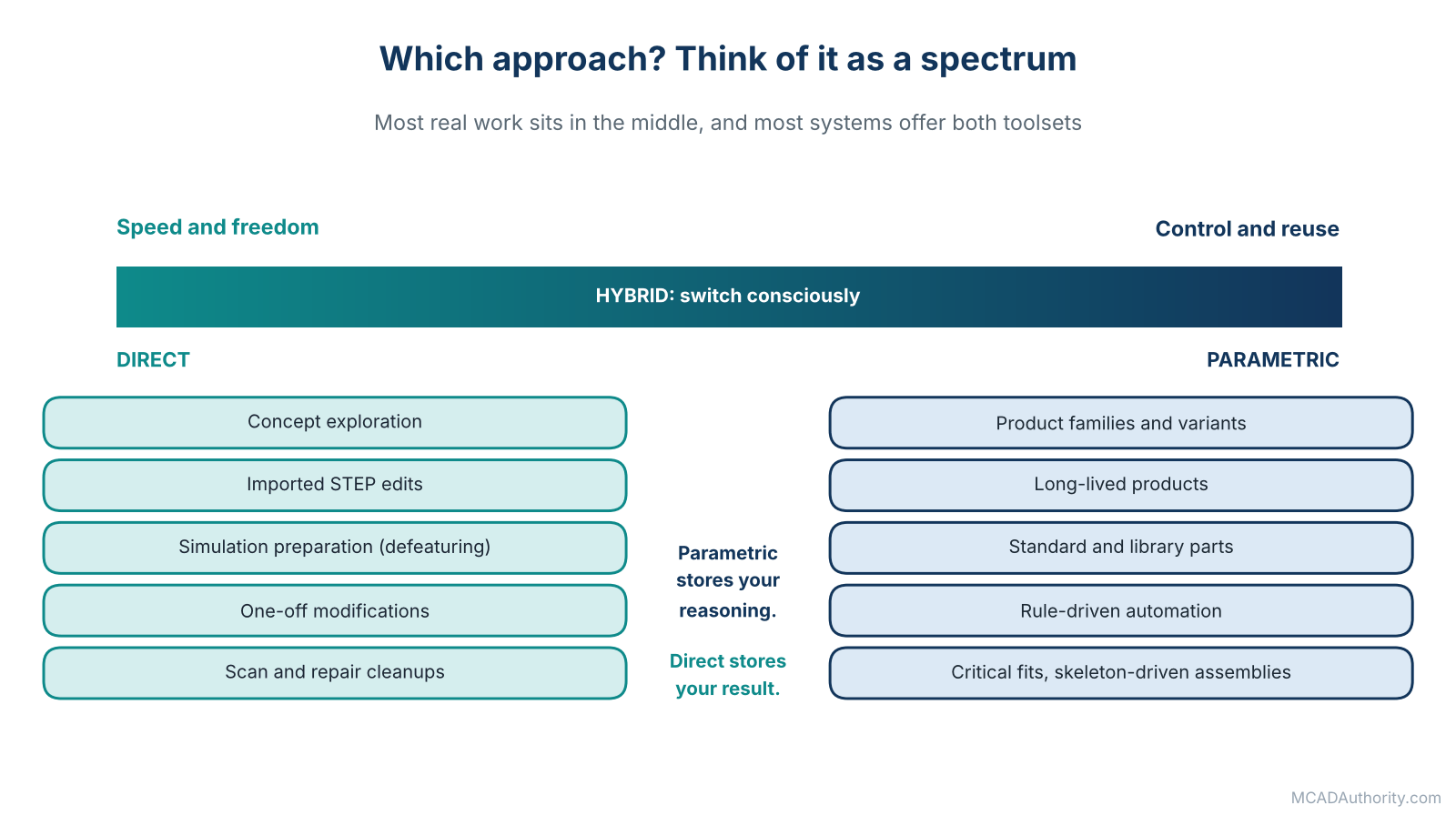
Figure 3. Direct modeling favors speed and freedom; parametric modeling favors control and reuse.
Practical Tips for Working Well in Either Style
Parametric tips
- Fully define sketches. Do not leave floating geometry.
- Reference stable geometry such as origin planes and sketches, not fragile edges or faces.
- Name important features and parameters clearly.
- Keep the feature tree short, ordered and readable.
- Build the most important features first, cosmetic ones last.
- Test your model by changing key dimensions before you release it.
Direct tips
- Save a version before major edits.
- Check related parts and drawings after each change.
- Add notes where the geometry hides an important relationship.
- Be careful with tangent and blended faces, where edits can have side effects.
- Recheck mass, clearances and critical dimensions after editing.
Final Thoughts
I have learned to distrust anyone who claims that one approach has defeated the other. What I have actually seen, over thirty years and across many systems, is that the best designers are bilingual. They build structured parametric models when control and reuse matter, and they switch to direct edits when freedom and speed matter more. They know the cost of each, and they choose consciously.
If you take only one idea from this guide, take this: parametric modeling stores your reasoning, direct modeling stores your result. When the reasoning matters, store it. When only the result matters, don’t waste time on ceremony.
Where to go next: continue with Understanding Design Intent in 3D Mechanical Modeling, which explains what “reasoning” really means inside a model, and then The Complete Mechanical CAD Workflow: From Concept to Manufacturing to see how these modeling styles fit into a full project.