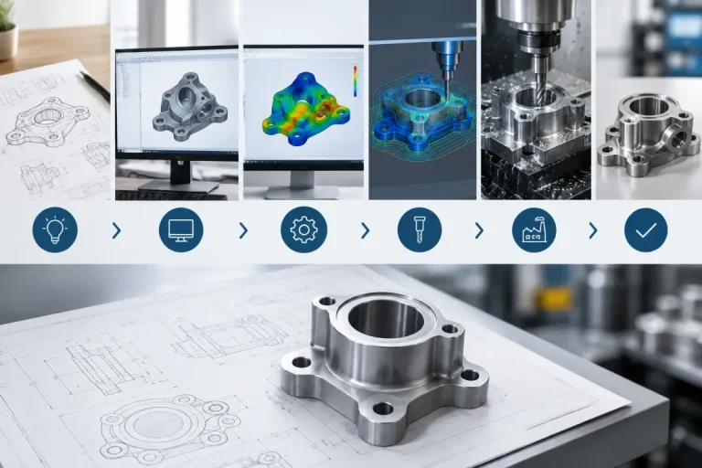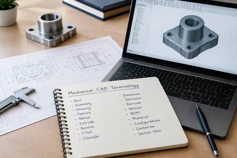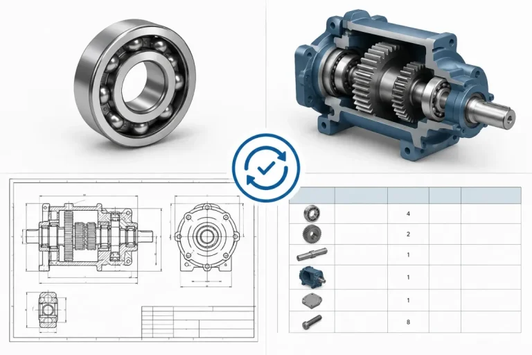



Early in my career as a CAD manager, a project engineer asked me to explain, in one sentence, what my department did for the company. I said: “We turn decisions into information that a factory can act on.” He frowned, then nodded. “So you’re not drawing. You’re translating.”
He was right, and twenty years later I still use that word. Every product, from a stainless steel food mixer to a medical pump to a packaging line, starts as a collection of decisions made by many people: marketing wants it smaller, the electronics team wants more space, the production manager wants fewer parts, the safety officer wants guards, the customer wants it cheaper. Mechanical CAD is where all those competing decisions are forced into a single, consistent, buildable description.
This guide shows how MCAD is used across the whole life of a product, from the first sketch to the service manual. I will walk you through each stage as it happens in real companies, point out where things typically go wrong, and show how modern tools, including Autodesk Inventor and Fusion, fit into the picture. If you are new to the subject, What Is Mechanical CAD (MCAD)? A Complete Beginner’s Guide gives the foundation, and Mechanical Product Development: From Concept to Production covers the management side in more depth.
The Short Answer
In modern product development, MCAD is used to:
- Explore and communicate concepts quickly and cheaply.
- Define the product in detail as parts, assemblies and their relationships.
- Verify the design virtually through interference checks, motion studies and simulation.
- Prepare the product for manufacturing with drawings, 3D data, bills of materials and process-specific models.
- Manage change and data throughout the product’s life.
- Support everything that happens after release: purchasing, assembly, quality, sales and service.
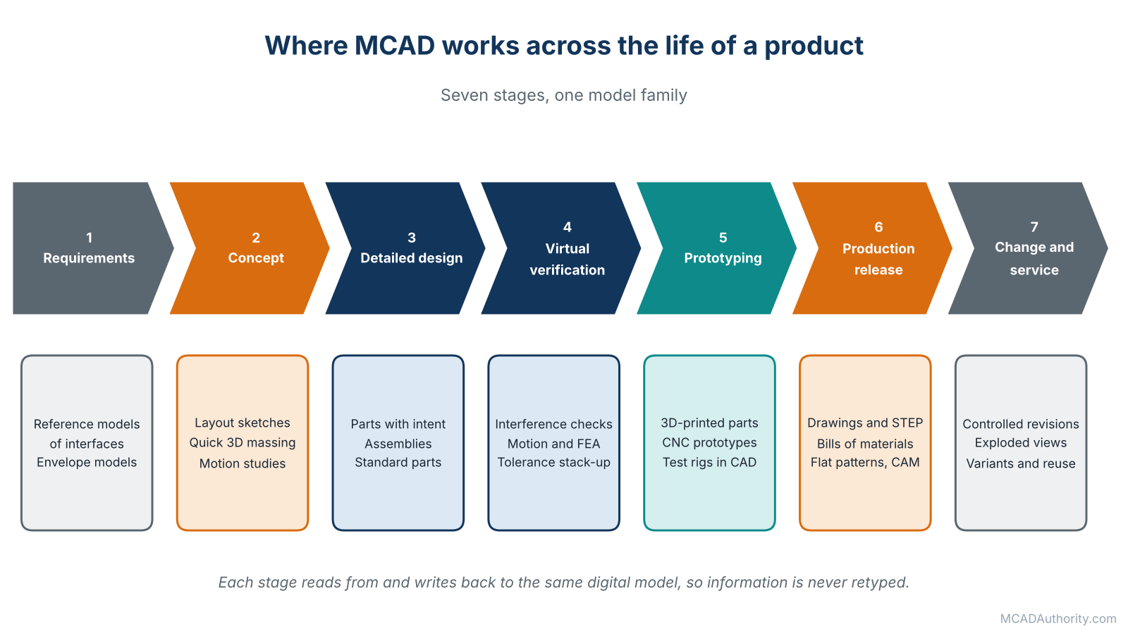
Figure 1. Where MCAD works across the life of a product.
The key idea is that the digital model becomes the central reference of the whole company, not just a drawing tool for one department.
Stage 1: Understanding What Must Be Built
A surprising amount of product development happens before anyone opens a CAD program. Good designers collect requirements first:
- Function: What must the product do? What loads, speeds, temperatures and cycles?
- Interfaces: What must it connect to, fit inside or work with?
- Environment: Dust, water, vibration, chemicals, outdoor use?
- Regulations and standards: Machinery safety rules, medical requirements, food contact materials, electrical standards.
- Cost and volume: One prototype, one hundred units, or a million?
- Manufacturing capability: What can your own workshop or your suppliers actually make?
I have seen teams skip this stage because “we know what the customer wants”, and I have seen the same teams redesign half their product three months later. A one-page requirements list that everyone has signed is the cheapest insurance in engineering.
Where MCAD helps here
Even at this stage, CAD supports the discussion. Reference models of existing equipment, buildings or interfaces can be imported to define the available space. Envelope models, simple boxes that represent the maximum allowed size of each module, let teams agree on boundaries before any detailed design begins.
Stage 2: Concept Design
Now ideas appear. The concept stage is about options, not precision. A designer may sketch several layouts, test different mechanisms and compare ways to reach the same function.
What CAD does in the concept stage
- Quick 3D massing. Rough shapes in 3D to explore proportions, ergonomics and layout.
- Layout sketches. Single sketches that define the main dimensions and mechanism positions, which later drive the detailed parts. This technique is explained in Skeleton Modeling and Master Layout Techniques.
- Kinematic studies. Simple mechanisms animated to check ranges of motion.
- Concept renderings. Images for management and customers to evaluate.
- Early cost thinking. Number of parts, material, rough manufacturing method.
A word of caution
The biggest mistake I see at this stage is over-detailing too early. A designer who spends three days modeling every fillet on a concept that will be rejected on Friday has wasted time. Keep concept models light and disposable. Some tools make this easier: direct modeling approaches, discussed in Parametric vs. Direct Modeling: Which Approach Is Better?, are often excellent for fast exploration because you can push and pull geometry without worrying about history.
Industrial design and surfaces
For consumer products, the concept often starts with industrial designers working in freeform surface tools. Their output is a beautiful shape, but not yet a manufacturable one. The mechanical designer’s job is to translate that shape into real parts with wall thickness, draft, ribs and assembly features. The techniques are covered in Surface Modeling in Mechanical CAD: A Complete Guide and Plastic Part Design: A Complete CAD Guide.
Stage 3: Detailed Design
This is the heart of MCAD work, where the product becomes real.
Building the parts
Each component is modeled as a solid, with features built from constrained sketches. The designer chooses the material, applies finishes, adds fillets and chamfers, and defines holes, threads and other manufacturing features. The quality of this work determines the quality of everything that follows. If you want to see how this is done properly, read Parametric 3D Modeling: A Complete Practical Guide.
Building the assemblies
Parts are brought together in assemblies using constraints or joints. A good assembly structure mirrors how the product is built and serviced, not just how it looks. I usually recommend organizing assemblies as logical subassemblies: a drive unit, a frame, a guard set, a control cabinet. Assembly Modeling in Mechanical CAD: A Complete Guide and Bottom-Up vs. Top-Down Assembly Design explain the approaches.
Using standard and purchased components
Almost no product is made entirely from custom parts. Motors, bearings, fasteners, sensors, cylinders and profiles come from catalogs. Modern MCAD systems include libraries of standard parts, and many suppliers provide downloadable models of their components. In practice, a significant share of a typical machine assembly is bought-in parts, and your CAD structure must distinguish them clearly from the parts you manufacture.
Designing with manufacturing in mind
Every design decision has a manufacturing consequence:
- A deep, narrow pocket may require a special tool and long machining time.
- A sharp internal corner cannot be milled.
- A plastic wall that is too thick causes sink marks and long cycle times.
- A sheet metal bend too close to a hole will distort it.
This is the domain of Design for Manufacturing (DFM) and Design for Assembly (DFA): A Complete Guide. In my experience, the designers who make the best products are those who regularly visit the workshop and listen to the people making their parts.
Capturing intent
As the design develops, the choices you make in sketches, constraints and features either capture your intent or hide it. Understanding Design Intent in 3D Mechanical Modeling is the guide I give to every new designer on my team, because a model that records why is worth far more than one that only records what.
Stage 4: Virtual Verification
Before spending money on prototypes, modern teams test the design on the computer. This is where MCAD pays for itself most visibly.
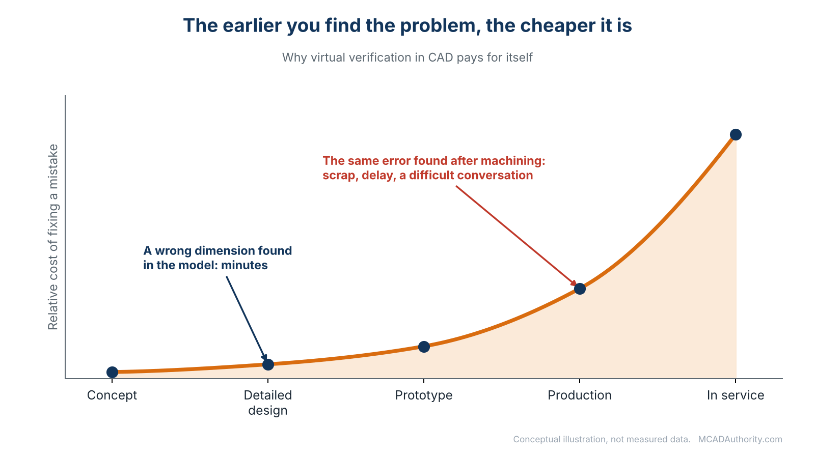
Figure 2. The earlier a problem is found, the cheaper it is to fix (conceptual illustration).
Interference and clearance checks
The software compares all parts in an assembly and highlights where they overlap or where gaps are too small. I have seen a single interference check find a collision between a motor cable and a moving carriage that would have been discovered only during commissioning, at the customer’s site.
Motion and kinematics
Mechanisms can be driven through their range, so you can see positions, velocities, collisions and reach. This is invaluable for linkages, robotic cells, doors, covers and any device with moving parts.
Ergonomics and access
Can an operator reach the button? Can a technician remove the filter without taking half the machine apart? Digital human models and simple clearance volumes answer these questions early.
Simulation (CAE)
Stress, deflection, thermal behavior, vibration and fluid flow can be studied using the CAD model as a starting point. A designer with basic simulation skills can quickly identify weak points and optimize weight. This area is introduced in Computer-Aided Engineering (CAE): A Complete Beginner’s Guide and Finite Element Analysis (FEA): Fundamentals for CAD Designers. For lightweight structures, newer approaches such as those described in Topology Optimization and Generative Design in Mechanical Engineering can suggest shapes a human might not consider.
Tolerance and fit analysis
A product works not because every part is perfect, but because the variations between parts stay within limits. Tolerance Stack-Up Analysis for Mechanical Assemblies shows how to check this on paper, and many CAD systems offer related tools.
The honest limit
Virtual verification reduces risk, but it does not eliminate it. A simulation is only as good as its assumptions. I always tell my teams: simulation tells you where to look, testing tells you what is true.
Stage 5: Prototyping
Even in a fully digital workflow, a physical prototype is often the moment of truth. MCAD has transformed how prototypes are made.
- 3D printing produces test parts overnight from the CAD model. See How to Prepare Mechanical CAD Models for 3D Printing.
- CNC machining can create functional prototypes in the actual material.
- Laser cutting and sheet metal workshops accept flat patterns generated from the 3D model.
- Fixtures and test rigs are designed in CAD and made quickly in-house.
Each prototype provides feedback. The cycle looks like this: design, build, test, learn, modify the model, repeat. Because the model drives everything, each iteration is faster and cheaper than in the paper era.
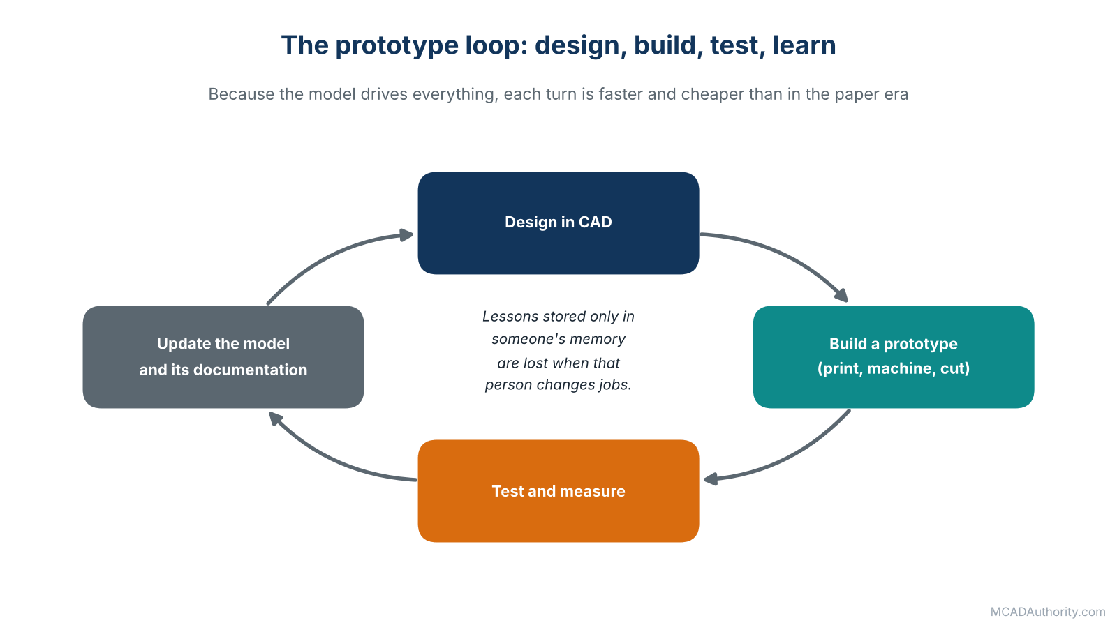
Figure 3. The prototype loop only works if lessons flow back into the model.
One practice I strongly recommend is recording what you learn directly in the model and its documentation. Prototype lessons stored only in someone’s memory will be lost the day that person changes jobs.
Stage 6: Preparing for Production
When the design is stable, MCAD produces the information that production needs.
Manufacturing drawings
Detailed drawings with dimensions, tolerances, materials, surface finishes and notes. They remain the contractual standard in most industries. See Mechanical Engineering Drawings: A Complete Guide and Geometric Dimensioning and Tolerancing (GD&T): A Complete Guide.
3D data for suppliers and machines
Neutral formats such as STEP carry geometry between different systems and companies. Increasingly, 3D models with embedded annotations are used in place of or alongside drawings, an approach introduced in Model-Based Definition (MBD) and 3D Product Manufacturing Information (PMI). The practical aspects of formats are in Mechanical CAD File Formats: A Complete Guide.
Bills of materials
The BOM lists every part, quantity, material and reference. It feeds purchasing, production planning and cost estimation. Getting it right is a discipline of its own, covered in Understanding Parts, Assemblies, Drawings, and BOMs in MCAD and Bill of Materials (BOM) Management in Mechanical CAD.
Process-specific models
Different manufacturing methods need specific derived data:
- Sheet metal: flat patterns and bend tables.
- Machined parts: models prepared for CAM, with toolpaths generated from them.
- Castings and molded parts: models with draft, shrinkage allowance and tooling splits.
- Welded frames: cut lists, weld symbols and assembly sequences.
- Additive parts: orientation, supports and build-specific preparation.
Assembly documentation
Exploded views, assembly drawings and work instructions help production teams build the product correctly and consistently.
Stage 7: Managing Data and Change
Here is where I have spent a good share of my career, and I will say it plainly: the technical work of design is usually not what causes a company the greatest pain. Uncontrolled data and uncontrolled change do.
Version and revision control
When twenty people share hundreds of interlinked files, you need a controlled environment. A PDM system, such as Autodesk Vault or equivalents from other vendors, manages check-in and check-out, versions, relationships between files and release status. Without it, someone will overwrite someone else’s work, and someone will manufacture from the wrong revision. See Product Data Management (PDM): A Complete Guide.
Engineering change management
After release, changes will happen. Customers request modifications, suppliers change components, production finds problems. A structured process, often with change requests and change orders, records what changed, why, who approved it and which documents were affected. See Engineering Change Requests (ECR) and Engineering Change Orders (ECO).
Standards and naming
Consistent file naming, part numbering, templates and drawing standards turn a collection of files into an organized library. They are the quiet foundation of a productive department. Mechanical CAD Standards: A Complete Guide and Mechanical CAD File Naming and Part Numbering Standards go into detail.
Stage 8: Beyond Release, Where the Model Keeps Working
A well-built model does not stop being useful when the product ships.
- Sales and marketing: renderings, animations and interactive visuals from the same data.
- Configuration: product families generated from parametric models and rules. See Mechanical CAD Automation: A Complete Guide.
- Service and maintenance: exploded views, spare parts lists, disassembly instructions.
- Quality control: inspection plans built from the model, comparing scanned or measured parts with the design.
- Customer support: quickly checking compatibility when someone requests a spare or an upgrade.
- Next-generation products: reuse of proven parts and sub-assemblies. Companies that treat their CAD library as an asset accelerate every future project.
- Reverse engineering: when you must recreate a part that has no model, scanning and rebuilding in CAD is a common route. See Reverse Engineering: From 3D Scanning to Editable CAD Models.
How Different Industries Use MCAD Differently
The stages are similar everywhere, but the emphasis shifts.
| Industry | What dominates the CAD work |
|---|---|
| Industrial machinery | Large assemblies, many standard parts, frames, guards, frequent customization |
| Automotive | Huge assemblies, surfacing, strict data control, supplier coordination |
| Aerospace | Lightweight structures, rigorous traceability and documentation |
| Medical devices | Precision parts, regulated records, links between design and quality documentation |
| Consumer products | Plastic enclosures, industrial design surfaces, tooling, cost per unit |
| Tooling and fixtures | Speed, one-off designs, close contact with the workshop |
| Energy and heavy equipment | Welded structures, large components, maintenance access |
The mechanical designer who understands the specifics of their industry, its standards, materials and typical failures, is far more valuable than one who only knows the software.
A Real-World Style Example: A Small Pump Assembly
To make this concrete, let me describe how a small industrial pump might move through the stages.
- Requirements. Flow rate, pressure, fluid type, motor power, mounting interface, cost target, ten thousand units per year.
- Concept. Three layouts compared in simple 3D, one chosen for its low part count.
- Detailed design. Housing designed as a casting, impeller modeled with surfaces, shaft and seals selected from catalogs, fasteners from the library.
- Verification. Interference check on the full assembly, stress analysis of the shaft, flow simulation of the housing.
- Prototype. 3D-printed housing for fit tests, machined impeller for performance tests.
- Production preparation. Casting drawings with draft and machining allowances, machining models for CAM, BOM for purchasing, assembly instructions.
- Change management. After first production, a seal supplier changes dimensions, an engineering change is released and documented.
- After release. Service manual with exploded views, spare parts catalog, variants for different motors.
Each stage uses the same model family. This continuity is what makes modern product development efficient. The detailed route through these steps is the topic of The Complete Mechanical CAD Workflow: From Concept to Manufacturing.
Common Problems in Product Development (And Their CAD Roots)
After many years of reviewing projects that went wrong, I find that the causes repeat.
- Requirements changing late. Fix: freeze requirements formally, and track changes.
- Late discovery of interference or assembly problems. Fix: assemble early and check often.
- Parts that cannot be manufactured economically. Fix: involve manufacturing early and apply DFM rules.
- Drawing errors and mismatches. Fix: generate drawings from models and review them carefully.
- Wrong revision in production. Fix: controlled release and data management.
- Models that no one can edit. Fix: modeling standards, clean feature trees and design reviews.
- Knowledge locked in one person’s head. Fix: documentation, templates and shared libraries.
- Tools chosen before needs were understood. Fix: define workflows first, then pick tools. See Best Mechanical CAD Software for Professional Engineers.
Notice that few of these are software problems. They are process, communication and discipline problems that software can either help or hide.
Where Product Development Is Heading
I stay cautious about hype, but several trends are real and worth knowing.
- Cloud collaboration. Teams share live models and comments in a browser. Trade-offs are discussed in Cloud-Based vs. Desktop Mechanical CAD: Advantages and Limitations.
- Model-based enterprise. The 3D model, with embedded annotations, becomes the master record, and drawings play a smaller role.
- Generative and optimization tools. Software proposes shapes that meet loads and constraints with less material.
- Automation. Rules and scripts generate variants and documents automatically.
- Tighter links with manufacturing. CAD, CAM and inspection data share a common thread.
- AI assistance. Useful for suggestions and repetitive tasks, but with real limits and risks, as discussed in Artificial Intelligence in Mechanical CAD: Applications and Limitations.
None of these eliminates the need for a designer who understands function, manufacturing and responsibility. They change the tools, not the craft.
What This Means For You
If you are learning CAD, do not only learn modeling. Learn the whole chain: how requirements become models, how models become drawings, how drawings become parts. That is what employers value.
If you manage a design team, look at your own process stage by stage. Where do errors occur? Where does time disappear? Where is information lost? Improve those points before buying new software.
If you run a small company, you do not need the full machinery of a large enterprise, but the same principles apply: clear requirements, a single source of truth, controlled change.
Final Thoughts
That project engineer who called us translators had it right. Product development is a long chain of translation: from a customer’s need into a requirement, from a requirement into a concept, from a concept into a model, from a model into a drawing, from a drawing into a physical object. At each step, information can be lost or distorted. Mechanical CAD, used well, is the discipline that keeps the meaning intact from the first idea to the finished product.
Take care of your models, your standards and your communication, and the technology will serve you. Neglect them, and even the most expensive software will simply help you make mistakes faster.
Where to go next: read The Complete Mechanical CAD Workflow: From Concept to Manufacturing for the step-by-step version of what I described here, and Parametric vs. Direct Modeling: Which Approach Is Better? to understand the two main ways models are built.